Hyundai Santa Fe (TM): Suspension System / Rear Suspension System
Components and components location
| Components |
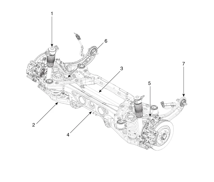
| 1. Rear shock
absorber 2. Rear lower arm 3. Rear stabilizer bar 4. Rear cross member |
5. Rear upper
arm 6. Rear assist arm 7. Trailing arm |
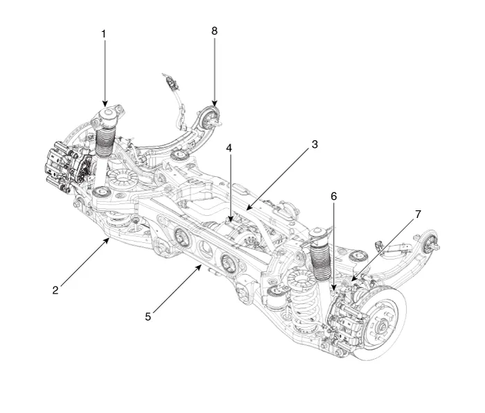
| 1. Rear shock
absorber 2. Rear lower arm 3. Rear stabilizer bar 4. Rear differential carrier |
5. Rear cross
member 6. Rear driveshaft 7. Rear upper arm 8. Trailing arm |
Rear Shock Absorber. Components and components location
| Components |
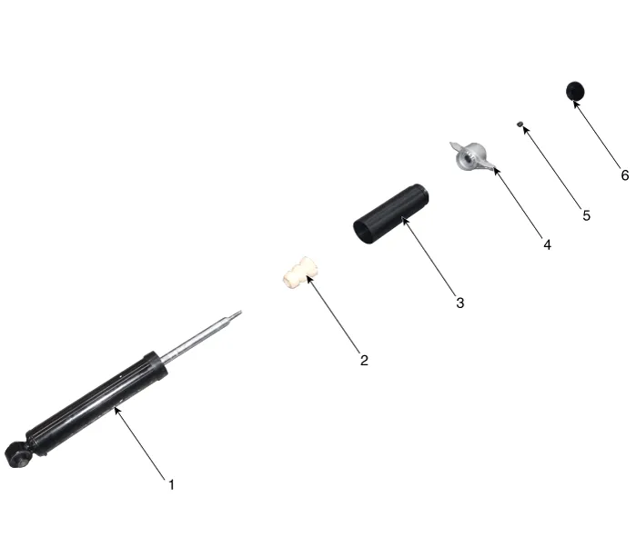
| 1. Rear shock
absorber 2. Dust cover 3. Bumper rubber |
4. Insulator
assembly 5. Lock nut 6. Insulator cap |
Rear Shock Absorber. Repair procedures
| Removal |
| 1. |
Loosen the wheel nuts slightly.
Raise the vehicle, and make sure it is securely supported.
|
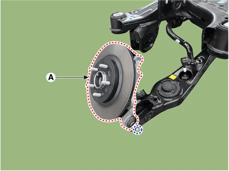
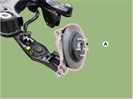
| 2. |
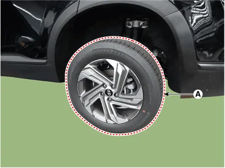
Remove the rear wheel and tire (A) from rear hub.
|

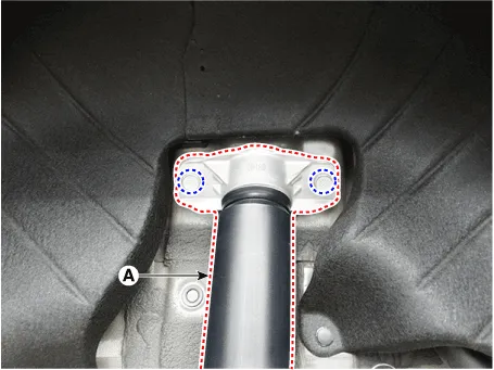
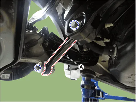
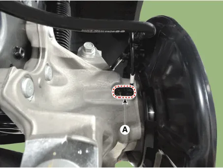
| 3. |
Remove the rear shock absorber (A) from the body by loosening the bolt.
|
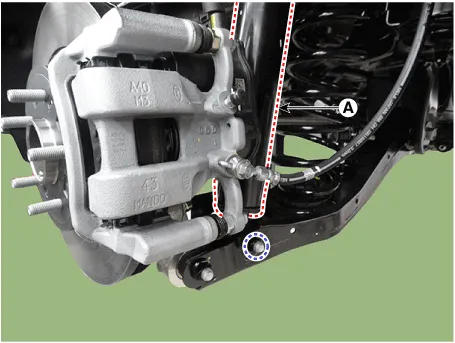
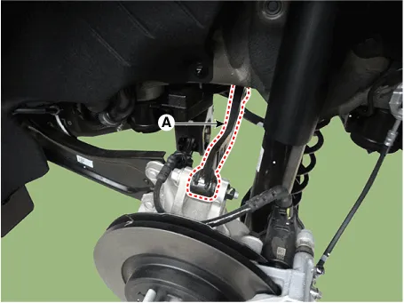
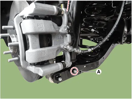
| 4. |
Loosen the bolt and nut and then remove the rear shock absorber (A)
from the lower arm.
|
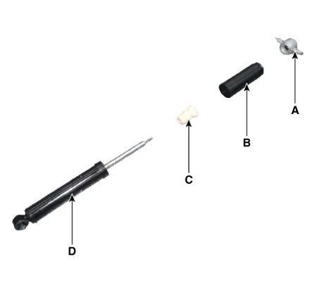
| Disassembly |
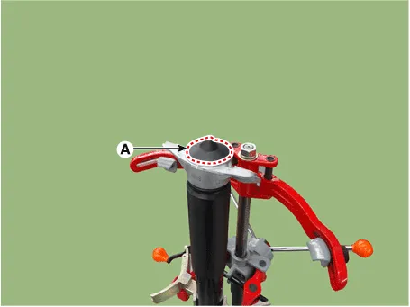
| 1. |
Remove the insulator cap (A).
|
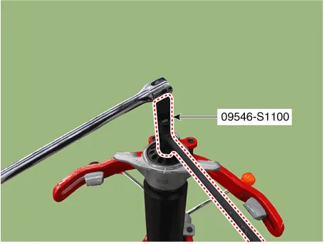
| 2. |
Using the special tool (09546-S1100), install the self locking nut.
|
| 3. |
Separate the Insulator assembly (A), dust cover (B), bumper rubber (C),
shock absorber (D).
|
| Inspection |
| 1. |
Check the rubber parts for damage or deterioration.
|
| 2. |
Check the shock absorber for abnormal resistance or unusual sounds.
|
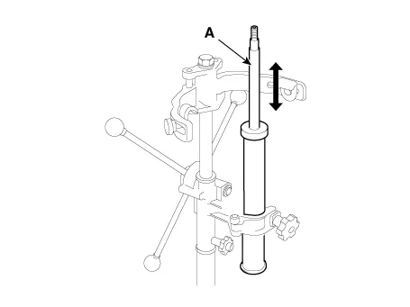
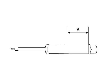
| Disposal |
| 1. |
Fully extend the shock absorber rod.
|
| 2. |
Drill a hole to remove gas from the cylinder.
|
| Reassembly |
| 1. |
To reassembly, reverse the disassembly procedure.
|
| 2. |
Using SST (09546-3X100), install the lock nut.
|
| 3. |
Install the lock nut cover (A).
|
| Installation |
| 1. |
To install, reverse the removal procedures.
|
Rear Upper Arm. Repair procedures
| Removal |
| 1. |
Loosen the wheel nuts slightly.
Raise the vehicle, and make sure it is securely supported.
|
| 2. |
Remove the rear wheel and tire (A) from rear hub.
|
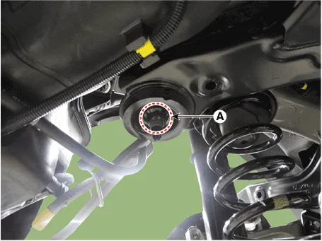
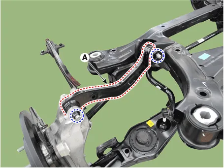
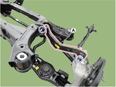
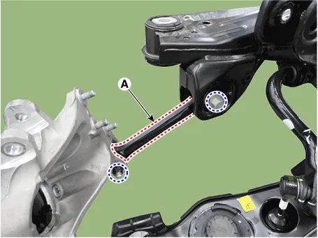
| 3. |
Remove the rear upper arm (A) after loosening the mounting bolt and
nut.
|
| Inspection |
| 1. |
Check the bushing for wear and deterioration.
|
| 2. |
Check the rear upper arm or damage and deformation.
|
| 3. |
Check for all bolts and nut.
|
| Installation |
| 1. |
To install, reverse the removal procedures.
|
| 2. |
Check the alignment.
(Refer to Suspension System - "Alingment")
|
Rear Lower Arm. Repair procedures
| Removal |
| 1. |
Loosen the wheel nuts slightly.
Raise the vehicle, and make sure it is securely supported.
|
| 2. |
Remove the rear wheel and tire (A) from rear hub.
|
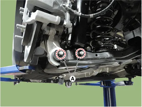
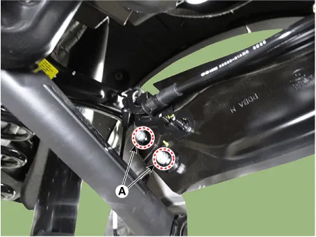
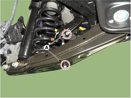
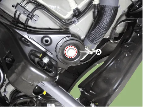
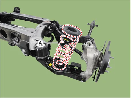
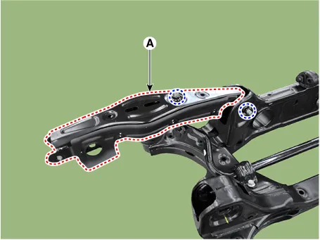
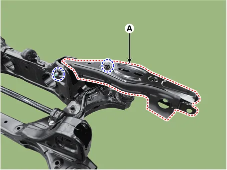
| 3. |
Remove the rear lower arm from the rear axle after loosening the mounting
bolts and nuts (A).
|
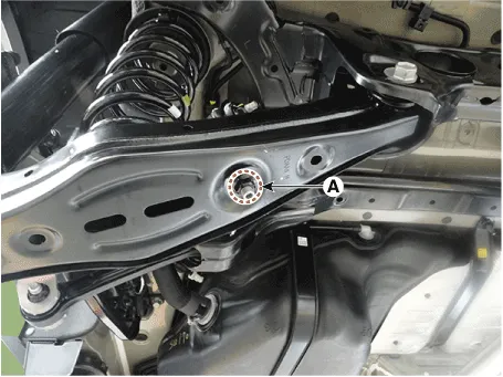
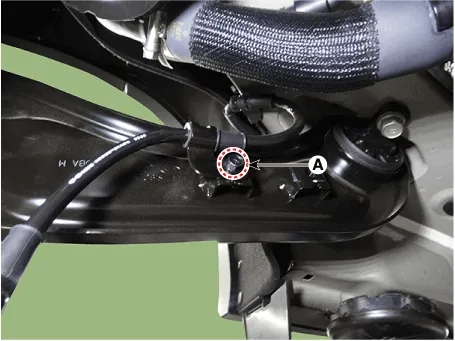
| 4. |
Remove the stabilizer bar link from the rear lower arm after loosening
the mounting nut (A).
|
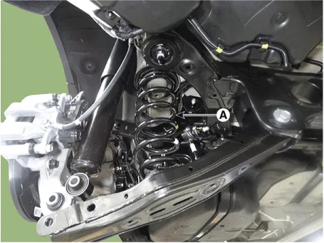
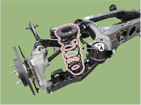
| 5. |
Remove the coil spring (A).
|
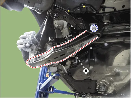
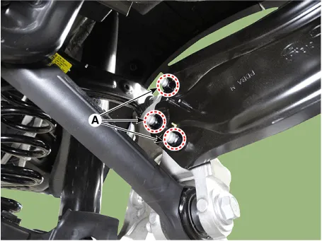
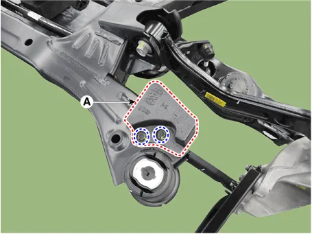
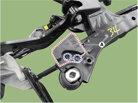
| 6. |
Remove the rear lower arm (A) after loosening the mounting bolt and
nut.
|
| Inspection |
| 1. |
Check the bushing for wear and deterioration.
|
| 2. |
Check the rear lower arm for deformation.
|
| 3. |
Check the coil spring and spring pad for deterioration and deformation.
|
| 4. |
Check for all bolts and nut.
|
| Installation |
| 1. |
To install, reverse the removal procedures.
|
| 2. |
Check the alignment.
(Refer to Suspension System - "Alingment")
|
Rear Coil Spring. Repair procedures
| Removal |
| 1. |
Loosen the wheel nuts slightly.
Raise the vehicle, and make sure it is securely supported.
|
| 2. |
Remove the rear wheel and tire (A) from rear hub.
|
| 3. |
Remove the rear lower arm from the rear axle after loosening the mounting
bolts and nuts (A).
|
| 4. |
Remove the stabilizer bar link from the rear lower arm after loosening
the mounting nut (A).
|
| 5. |
Remove the coil spring (A).
|
| Inspection |
| 1. |
Check the spring for distortion, aging or damage.
|
| 2. |
Check the spring upper pad and lower pad for aging or damage.
|
| Installation |
| 1. |
To install, reverse the removal procedures.
|
| 2. |
Check the alignment.
(Refer to Suspension System - "Alingment")
|
Trailing Arm. Repair procedures
| Removal |
| 1. |
Loosen the wheel nuts slightly.
Raise the vehicle, and make sure it is securely supported.
|
| 2. |
Remove the rear wheel and tire (A) from rear hub.
|
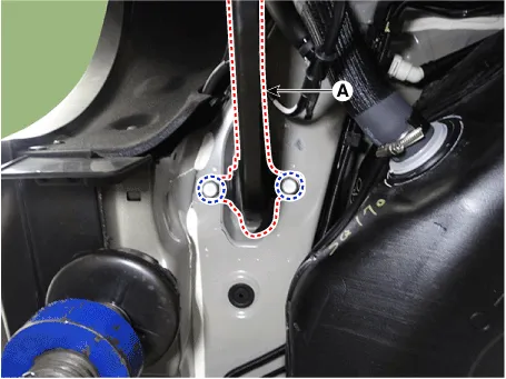
| 3. |
Loosen the wheel speed sensor cable bracket mounting nuts (A).
|
| 4. |
Loosen the wheel speed sensor cable bracket mounting bolts (A).
|
| 5. |
Loosen the trailing arm mounting bolts (A).
|
| 6. |
Remove the trailing arm (A) after loosening the mounting bolts.
|
| Inspection |
| 1. |
Check the bushing for wear and deterioration.
|
| 2. |
Check for all bolts and nuts.
|
| Installation |
| 1. |
To install, reverse the removal procedures.
|
| 2. |
Check the alignment.
(Refer to Suspension System - "Alingment")
|
Rear Assist Arm. Repair procedures
| Removal |
| 1. |
Loosen the wheel nuts slightly.
Raise the vehicle, and make sure it is securely supported.
|
| 2. |
Remove the rear wheel and tire (A) from rear hub.
|
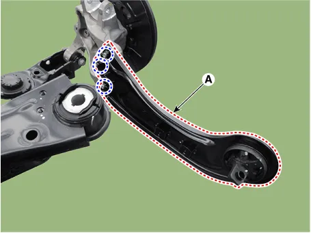
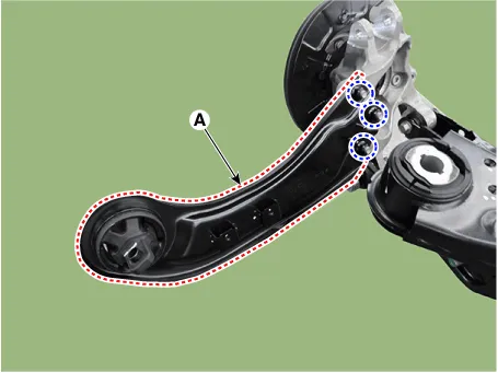
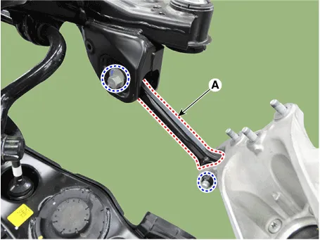
| 3. |
Remove the rear assist arm (A) after loosening the mounting bolts and
nuts.
|
| Inspection |
| 1. |
Check the bushing for wear and deterioration.
|
| 2. |
Check for all bolts and nuts.
|
| Installation |
| 1. |
To install, reverse the removal procedures.
|
| 2. |
Check the alignment.
(Refer to Suspension System - "Alingment")
|
Rear Stabilizer Bar. Repair procedures
| Removal |
| 1. |
Raise the vehicle, and make sure it is securely supported.
|
| 2. |
In the case of 4WD vehicle, remove the rear differential assembly.
(Refer to Driveshaft and axle - "Rear Differential Carrier")
|
| 3. |
Remove the rear stabilizer link after loosening the mounting nut (A).
|
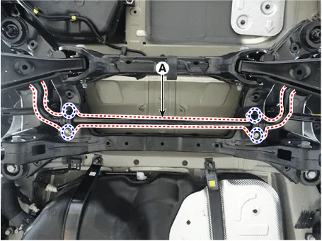
| 4. |
Remove the rear stabilizer bar (A) after loosening the mounting bolts.
|
| Inspection |
| 1. |
Check the rear stabilizer bar for deformation.
|
| 2. |
Check the rear stabilizer link ball joint for damage.
|
| Installation |
| 1. |
To install, reverse the removal procedures.
|
| 2. |
Check the alignment.
(Refer to Suspension System - "Alingment")
|
Rear Cross Member. Repair procedures
| Removal |
| 1. |
Loosen the wheel nuts slightly.
Raise the vehicle, and make sure it is securely supported.
|
| 2. |
Remove the front wheel and tire (A) from the front hub.
|
| 3. |
Remove the rear brake caliper.
(Refer to Brake System - "Rear Disc Brake")
|
| 4. |
In the case of 4WD vehicle, remove the rear differential assembly.
(Refer to Driveshaft and axle - "Rear Differential Carrier")
|
| 5. |
Remove the center muffler.
(Refer to Engine Mechanical System - "Muffler")
|
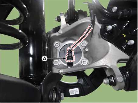
| 6. |
Disconnect the rear wheel speed sensor connector (A).
[2WD]
|
| 7. |
Remove the rear wheel speed sensor (A) after loosening the mounting
bolt.
[4WD]
|
| 8. |
Loosen the wheel speed sensor cable bracket mounting nuts (A).
|
| 9. |
Loosen the wheel speed sensor cable bracket mounting bolts (A).
|
| 10. |
Remove the trailing arm (A) after loosening the mounting bolts.
|
| 11. |
Support the jack on the lower part of the cross member.
|
| 12. |
Loosen the bolt and nut and then remove the rear shock absorber (A)
from the lower arm.
|
| 13. |
|
| 14. |
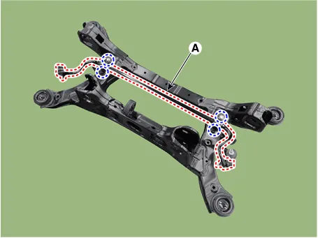
Loosen the cross member mounting bolts (A).
|
| 15. |
Remove the rear cross member.
|
| 16. |
Remove the coil spring (A).
[LH]
[RH]
|
| 17. |
Remove the damper (A) after loosening the mounting bolts.
[LH]
[RH]
|
| 18. |
Remove the rear upper arm (A) after loosening the mounting bolts and
nuts.
[LH]
[RH]
|
| 19. |
Remove the trailing arm (A) after loosening the mounting nuts.
[LH]
[RH]
|
| 20. |
Remove the rear assist arm (A) after loosening the mounting bolts and
nuts.
[LH]
[RH]
|
| 21. |
Remove the rear carrier (A) from the rear lower arm after loosening
the mounting bolt and nut.
[LH]
[RH]
|
| 22. |
Remove the rear lower arm (A) after loosening the mounting bolts and
nuts.
[LH]
[RH]
|
| 23. |
Remove the rear stabilizer bar (A) after loosening the mounting bolts.
|
| Inspection |
| 1. |
Check the bushing for wear and deterioration.
|
| 2. |
Check for all bolts and nuts.
|
| Installation |
| 1. |
To install, reverse the removal procedures.
|
| 2. |
Check the alignment.
(Refer to Suspension System - "Alingment")
|
Components and components location Components Location 1. Front sub frame 2. Drive shaft 3. Steering gear box 4.
Tire. Repair procedures Tire Wear • Using tires and wheel other than the recommended sizes could cause unusual handling characteristics and poor vehicle control, resulting in a serious accident.
Other information:
Hyundai Santa Fe (TM) 2019-2023 Service and Repair Manual: Description and operation
Description and operation The System may be limited when • The radar sensor or camera is blocked with a foreign object or debris.
Hyundai Santa Fe (TM) 2019-2023 Service and Repair Manual: Surround View Monitor (SVM)
Description and operation Description Surround View Monitor (SVM) is the system that allows video monitoring of 360 degrees around the vehicle. The system includes 4 ultra optical camera mounted around the vehicle (front, both sides, rear).
Categories
- Manuals Home
- Hyundai Santa Fe Owners Manual
- Hyundai Santa Fe Service Manual
- Rear Disc Brake. Repair procedures
- Power Tailgate Module
- Engine Electrical System
- New on site
- Most important about car
