Hyundai Santa Fe (TM): Driveshaft and axle / Front Hub / Knuckle / Tone Wheel
Components and components location
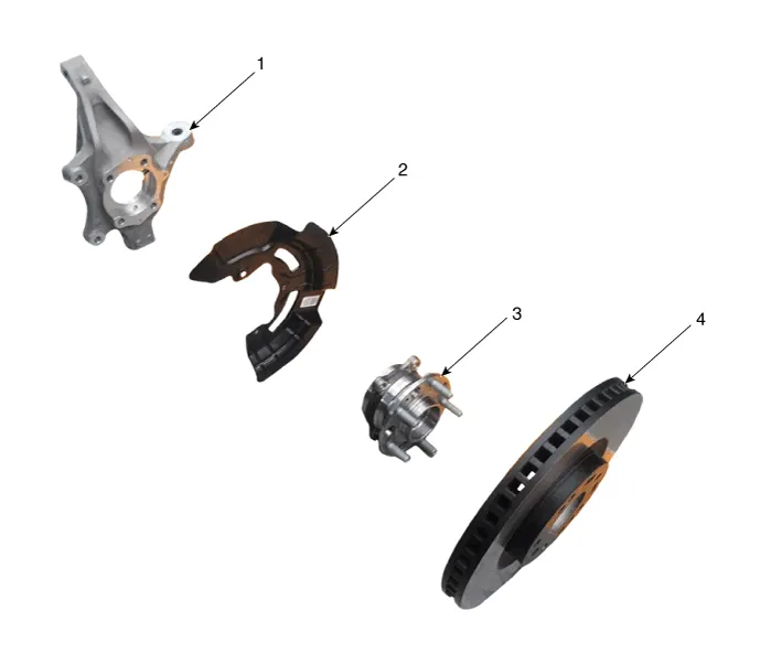
| Components |
|
1. Front knuckle 2. Dust cover |
3. Front hub assembly 4. Front brake disc |
Repair procedures
| Removal |
|

| 1. |
Loosen the wheel nuts slightly.
Raise the vehicle, and make sure it is securely supported.
|
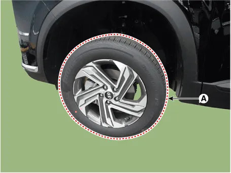
| 2. |
Remove the front wheel and tire (A) from the front hub.
|

| 3. |
Remove the front brake caliper.
(Refer to Brake System - "Front Disc Brake")
|
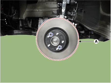
| 4. |
Loosen the screw and then remove the front disc (A).
|
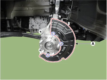
| 5. |
Remove the dust cover (A).
|
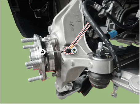
| 6. |
Remove the wheel speed sensor (A) from the knuckle after loosening the
mounting bolt.
|
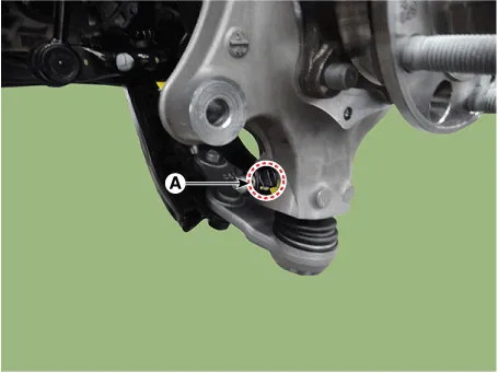
| 7. |
Remove the split pin and nut (A).
|
| 8. |
Remove the lower arm from the knuckle by using the SST (09568-4R100).
|
| 9. |
Remove the split pin and nut (A).
|
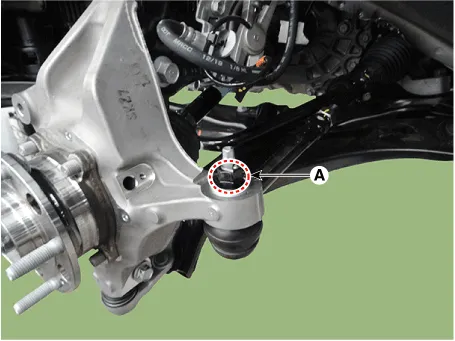
| 10. |
Remove the tie rod end ball joint (A) using the SST (09568-2J100).
|
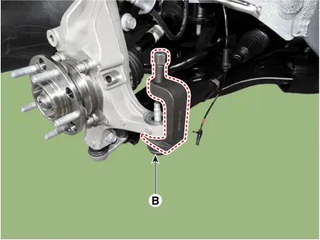
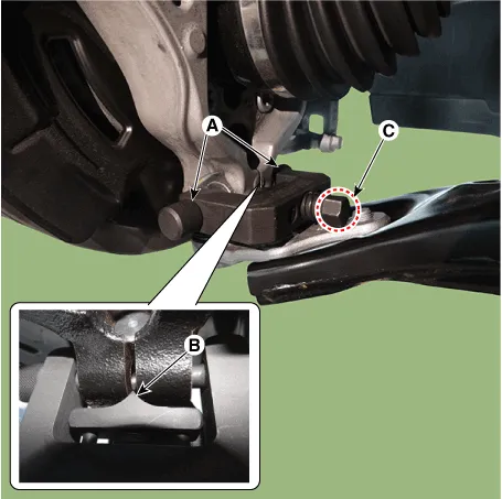
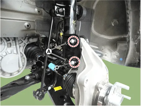
| 11. |
Remove the front strut assembly mounting bolts and nuts (A) from the
front axle.
|
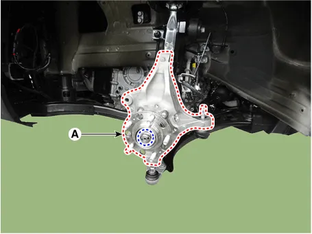
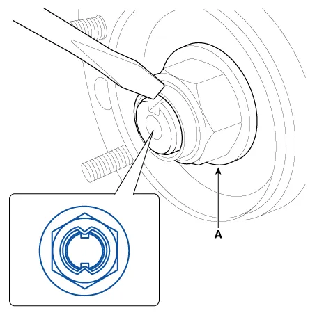
| 12. |
Remove the front knuckle & front hub bearing (A) after loosening the
caulking nut.
|
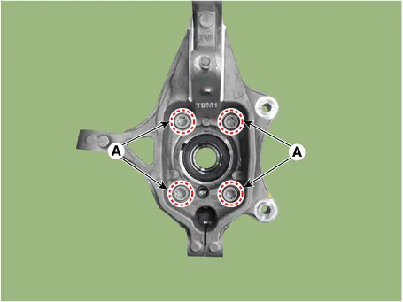
| 13. |
Remove the front hub bearing from the front knuckle after loosening
the mounting bolts (A).
|
| Inspection |
| 1. |
Check the hub for cracks and the splines for wear.
|
| 2. |
Check the brake disc for scoring and damage.
|
| 3. |
Check the knuckle for cracks.
|
| 4. |
Check the bearing for cracks or damage.
|
| Installation |
| 1. |
To install, reverse the removal procedures.
|
| 2. |
Check the alignment.
(Refer to Suspension System - "Alingment")
|
Special Service Tools Tool(Number and Name) Illustration Use Ball joint puller 09568-2J100 Use for removal of ball joint Lower arm ball joint remover 09568-4R100 Removal of the lower arm ball joint.
Front Driveshaft. Components and components location Components 1. Front driveshaft (LH) 2. Inner shaft bearing bracket 3.
Other information:
Hyundai Santa Fe (TM) 2019-2023 Service and Repair Manual: Power Tailgate Module
Description and operation Description Power tailgate is an electro-mechanical system designed to provide power opening and closing of the tailgate through the push of a button of a remote key (fob), console switch, inner switch or an outside handle switch of the tailgate.
Hyundai Santa Fe (TM) 2019-2023 Service and Repair Manual: Description and operation
Description and operation The System may be limited when • The radar sensor or camera is blocked with a foreign object or debris.
Categories
- Manuals Home
- Hyundai Santa Fe Owners Manual
- Hyundai Santa Fe Service Manual
- Troubleshooting
- Front Radar Unit. Repair procedures
- Lane Following Assist (LFA)
- New on site
- Most important about car
