Hyundai Santa Fe: Engine And Transaxle Assembly / Engine And Transaxle Assembly. Repair procedures
Hyundai Santa Fe (TM) 2019-2025 Service Manual / Engine Mechanical System / Engine And Transaxle Assembly / Engine And Transaxle Assembly. Repair procedures
| Removal |
|
|
|
| 1. |
Disconnect the battery negative terminal.
|
| 2. |
Remove the engine cover.
(Refer to Engine And Transaxle Assembly - "Engine Cover")
|
| 3. |
Remove the air duct and air cleaner assembly.
(Refer to Intake and Exhaust System - "Air Cleaner")
|
| 4. |
Remove the battery and battery tray.
(Refer to Engine Electrical System - "Battery")
|
| 5. |
Remove the engine room under corver.
(Refer to Engine And Transaxle Assembly - "Engine Room Under Cover")
|
| 6. |
Loosen the drain plug and drain the coolant.
(Refer to Cooling System - "Coolant")
|
| 7. |
Recover the refrigerant and then remove the high pressure pipe and low
pressure pipe.
(Refer to Heateng, Ventilation, Air conditioning - "Compressor")
|
| 8. |
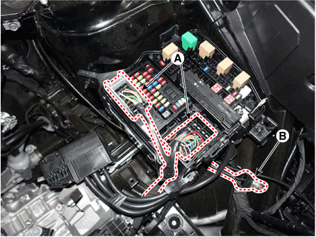
Disconnect the fuse box connectors (A) and ground cable (B).
|
| 9. |
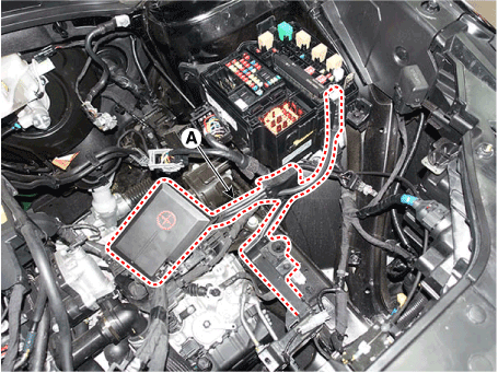
Disconnect the (+) wiring cable (A).
|
| 10. |
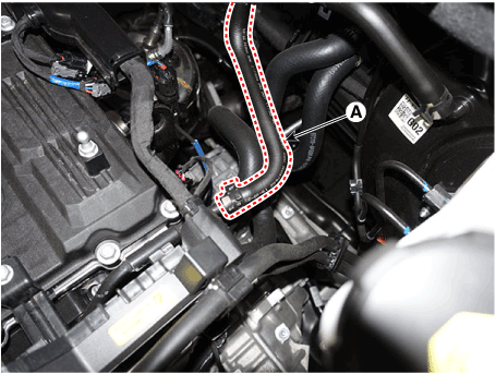
Disconnect the brake booster vacuum hose (A).
|
| 11. |
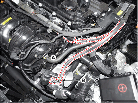
Disconnect the fuel hose (A) and the purge control solenoid valve (PCSV)
hose (B).
|
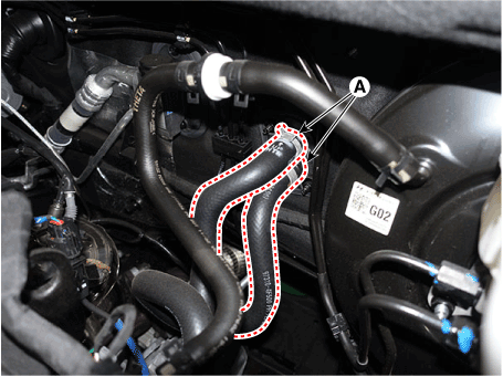
| 12. |
Disconnect the heater hoses (A).
|
| 13. |
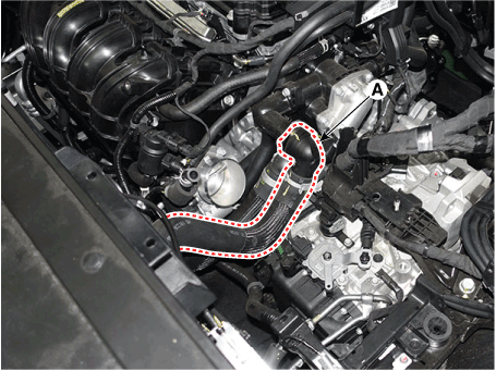
Disconnect the radiator upper hose (A).
|
| 14. |
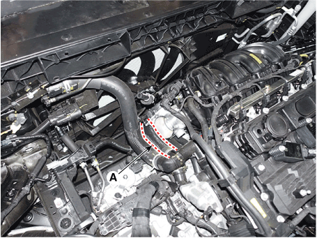
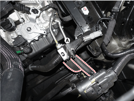
Disconnect the raditor lower hose (A).
|
| 15. |
Remove the front muffler.
(Refer to Intake and Exhaust System - "Muffler")
|
| 16. |
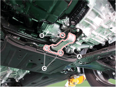
Remove the roll rod bracket (A).
|
| 17. |
Remove the roll rod support bracket (A).
|
| 18. |
Remove the sub frame assembly.
(Refer to Suspension System - "Sub Frame")
|
| 19. |
Support the engine and transaxle assembly with a floor jack.
|
| 20. |
Remove the steering U-joint mounting bolts.
(Refer to Steering System - "Steering Column and Shaft")
|
| 21. |
Remove the engine ground cable (A).
|
| 22. |
Disconnect the ground cable (A).
|
| 23. |
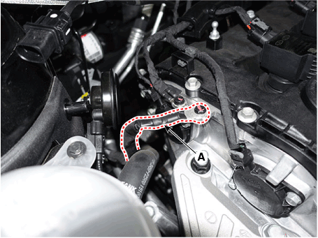
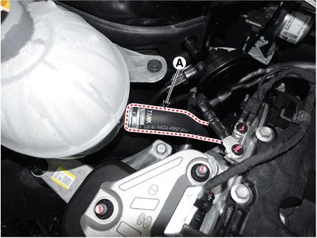
Disconnect the reservoir tank water hose (A).
|
| 24. |
Disconnect the ATF cooler hoses (A).
|
| 25. |
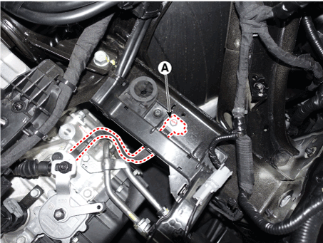
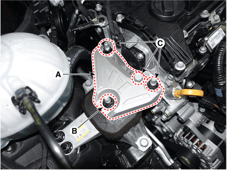
Remove the engine mounting support bracket (A).
|
| 26. |
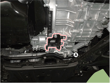
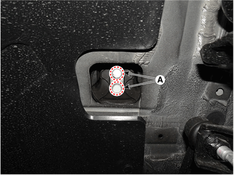
Remove the transaxle mounting bracket through bolt (A).
|
| 27. |
Remove the engine and transaxle assembly by lifting vehicle.
|
| 28. |
Install in the reverse order of removal.
|
 Engine Mounting. Repair procedures
Removal and Installation
•
Be careful not to damage the parts located under the vehicle
(floor under cover, fuel filter, fuel tank and canister) when
raising the vehicle using the lift...
Other information:
Hyundai Santa Fe (TM) 2019-2025 Service Manual: Blower Unit. Repair procedures
Replacement 1. Disconnect the negative (-) battery terminal. 2. Recover the refrigerant with a recovery/recycling/charging station. 3. When the engine is cool, drain the engine coolant from the radiator...
Hyundai Santa Fe (TM) 2019-2025 Owner's Manual: Interior Overview
1. Inside door handle 2. Power window switches 3. Power window lock button/Electronic child safety lock button 4. Side view mirror folding button 5. Side view mirror control switch 6. Central door lock switch 7. Instrument panel illumination control switch 8...
Categories
- Manuals Home
- 4th Generation Santa Fe Owners Manual
- 4th Generation Santa Fe Service Manual
- Warning and indicator lights
- Head-up display settings
- Electronic child safety lock
- New on site
- Most important about car
Air bag collision sensors
WARNING
To reduce the risk of an air bag deploying unexpectedly and causing serious injury or death:
Do not hit or allow any objects to impact the locations where air bags or sensors are installed. Do not perform maintenance on or around the air bag sensors. If the location or angle of the sensors is altered, the air bags may deploy when they should not or may not deploy when they should. Installing bumper guards with nongenuine Hyundai or non-equivalent parts may adversely affect the collision and airbag deployment performance. Press the Engine Start/Stop button to the OFF or ACC position and wait for 3 minutes when the vehicle is being towed to prevent inadvertent air bag deployment. Have all air bag repairs performed by an authorized HYUNDAI dealer.
Copyright © 2025 www.hsafe4.com


