Hyundai Santa Fe (TM): Engine Mechanical System / Engine And Transaxle Assembly
Engine Cover. Repair procedures
| Removal and Installation |
| 1. |
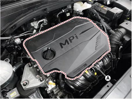
Remove the engine cover (A).
|

| 2. |
Install in the reverse order of removal.
|
Engine Room Under Cover. Repair procedures
| Removal and Installation |
|

| 1. |
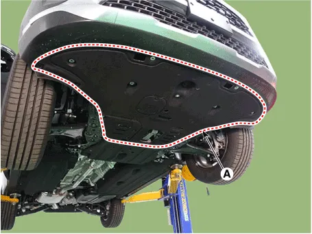
Remove the engine room under cover (A).
|
| 2. |
Install in the reverse order of removal.
|
| 1. |
Remove the engine room rear under cover (A).
|

| 2. |
Install in the reverse order of removal.
|
Engine Mounting. Components and components location
| Components |
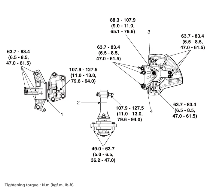
| 1. Transaxle
mounting bracket 2. Roll rod bracket |
3. Engine mounting
bracket 4. Engine mounting support bracket |
Engine Mounting. Repair procedures
| Removal and Installation |
|
| 1. |
Remove the engine room under cover.
(Refer to Engine And Transaxle Assembly - "Engine Room Under Cover")
|
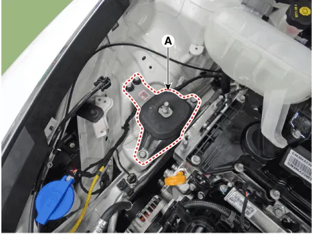
| 2. |
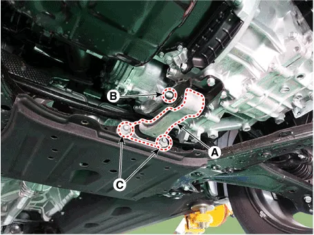
Remove the roll rod bracket (A).
|
| 3. |
Remove the roll rod mounting support bracket (A).
|
| 1. |
Remove the engine room under cover.
(Refer to Engine and transaxle Assembly - "Engine Room Under Cover")
|
| 2. |
Remove the engine cover.
(Refer to Engine and transaxle Assembly - "Engine Cover")
|
| 3. |
Install the jack to the edge of oil pan to support the engine.
|
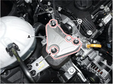
| 4. |
Remove the engine mounting support bracket (A).
|
| 5. |
Remove the reservoir tank.
(Refer to Cooling System - "Reservoir Tank")
|
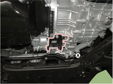
| 6. |
Remove the engine mounting bracket (A).
|
| 7. |
Install in the reverse order of removal.
|
| 1. |
Remove the engine room under cover.
(Refer to Engine And Transaxle Assembly - "Engine Room Under Cover")
|
| 2. |
Remove the air duct.
(Refer to Intake and Exhaust System - "Air Cleaner")
|
| 3. |
Remove the air cleaner assembly.
(Refer to Intake and Exhaust System - "Air Cleaner")
|
| 4. |
Remove the battery and tray.
(Refer to Engine Electrical System - "Battery")
|
| 5. |
Install the jack to the edge of transaxle.
|
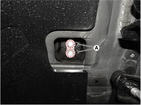
| 6. |
Remove the transaxle mounting bolts (A).
|
| 7. |
Remove the transaxle mounting bracket (A).
|
| 8. |
Install in the reverse order of removal.
|
Engine And Transaxle Assembly. Repair procedures
| Removal |
|
|
|
| 1. |
Disconnect the battery negative terminal.
|
| 2. |
Remove the engine cover.
(Refer to Engine And Transaxle Assembly - "Engine Cover")
|
| 3. |
Remove the air duct and air cleaner assembly.
(Refer to Intake and Exhaust System - "Air Cleaner")
|
| 4. |
Remove the battery and battery tray.
(Refer to Engine Electrical System - "Battery")
|
| 5. |
Remove the engine room under corver.
(Refer to Engine And Transaxle Assembly - "Engine Room Under Cover")
|
| 6. |
Loosen the drain plug and drain the coolant.
(Refer to Cooling System - "Coolant")
|
| 7. |
Recover the refrigerant and then remove the high pressure pipe and low
pressure pipe.
(Refer to Heateng, Ventilation, Air conditioning - "Compressor")
|
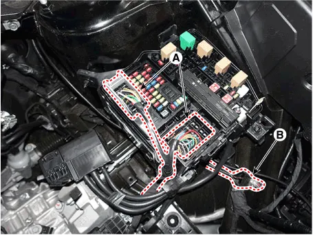
| 8. |
Disconnect the fuse box connectors (A) and ground cable (B).
|
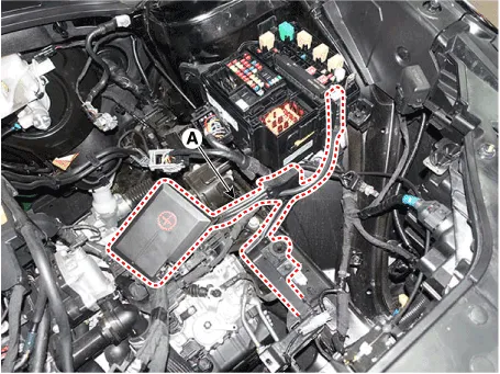
| 9. |
Disconnect the (+) wiring cable (A).
|
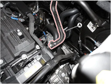
| 10. |
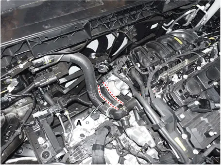
Disconnect the brake booster vacuum hose (A).
|
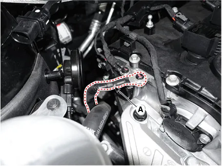
| 11. |
Disconnect the fuel hose (A) and the purge control solenoid valve (PCSV)
hose (B).
|
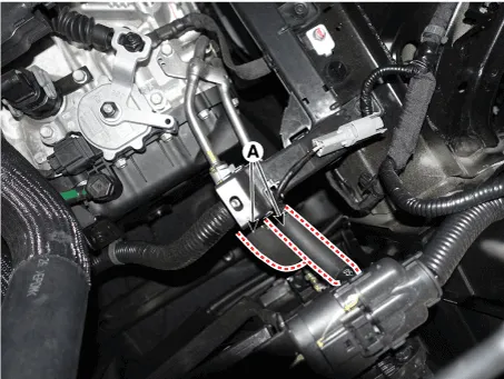
| 12. |
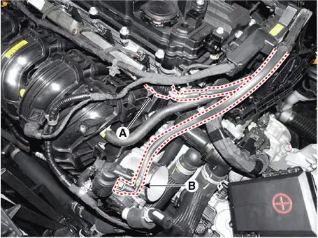
Disconnect the heater hoses (A).
|
| 13. |
Disconnect the radiator upper hose (A).
|
| 14. |
Disconnect the raditor lower hose (A).
|
| 15. |
Remove the front muffler.
(Refer to Intake and Exhaust System - "Muffler")
|
| 16. |
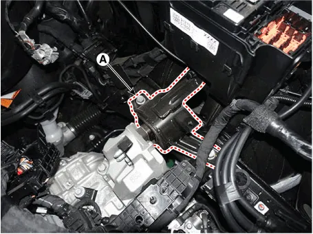
Remove the roll rod bracket (A).
|
| 17. |
Remove the roll rod support bracket (A).
|
| 18. |
Remove the sub frame assembly.
(Refer to Suspension System - "Sub Frame")
|
| 19. |
Support the engine and transaxle assembly with a floor jack.
|
| 20. |
Remove the steering U-joint mounting bolts.
(Refer to Steering System - "Steering Column and Shaft")
|
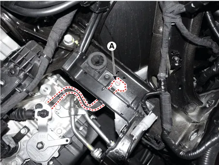
| 21. |
Remove the engine ground cable (A).
|
| 22. |
Disconnect the ground cable (A).
|
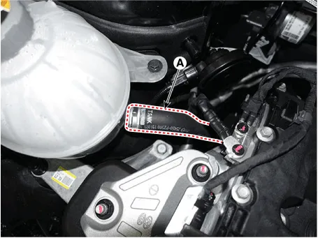
| 23. |
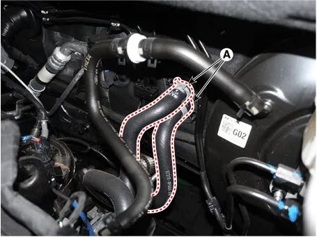
Disconnect the reservoir tank water hose (A).
|
| 24. |
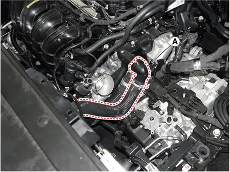
Disconnect the ATF cooler hoses (A).
|
| 25. |
Remove the engine mounting support bracket (A).
|
| 26. |
Remove the transaxle mounting bracket through bolt (A).
|
| 27. |
Remove the engine and transaxle assembly by lifting vehicle.
|
| 28. |
Install in the reverse order of removal.
|
Troubleshooting Symption Suspect area Remedy Engine misfire with abnormal internal lower engine noises.
Drive Belt. Repair procedures Removal • Be careful not to damage the parts located under the vehicle (floor under cover, fuel filter, fuel tank and canister) when raising the vehicle using the lift.
Other information:
Hyundai Santa Fe (TM) 2019-2023 Service and Repair Manual: Indicators And Gauges
Troubleshooting Troubleshooting Symptom Possible cause Remedy Speedometer does not operate Cluster fuse (10A) blown Check for short and replace fuse Speedometer faulty Check speedometer CAN line faulty
Hyundai Santa Fe (TM) 2019-2023 Service and Repair Manual: Rear Occupant Alert
Description and operation Description The system detects the passenger in the vehicle and prevents the driver from getting off the vehicle with the passenger in the back. - 1st warning: If you open the driver's door after you open and then close the rear passenger and turn the engine off, the system provides warn
Categories
- Manuals Home
- Hyundai Santa Fe Owners Manual
- Hyundai Santa Fe Service Manual
- Lane Following Assist (LFA)
- Vehicle auto-shut off. System Operation
- Blower
- New on site
- Most important about car
