
Hyundai Santa Fe (TM): Engine Mechanical System / Drive Belt System
Drive Belt. Repair procedures
| Removal |
|

| 1. |
Remove the front tire.
(Refer to Suspension System - "Wheel")
|
| 2. |
Remove the engine room under cover.
(Refer to Engine And Transaxle Assembly - "Engine Room Under Cover")
|
| 3. |
Remove the RH front wheel guard.
(Refer to Body (Interior and Exterior) - "Front Wheel Guard")
|
| 4. |
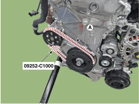
For release the tension, turn the drive belt tensioner clockwise using
a wrench then remove the drive belt (A).
|

| 5. |
Remove the water pump belt.
|
| Installation |
| 1. |
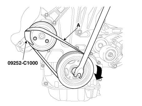
Install the water pump belt.
|
| 2. |
For release the tension, turn the drive belt tensioner clockwise using
a wrench then install the drive belt (A).
|
| Inspection |
| 1. |
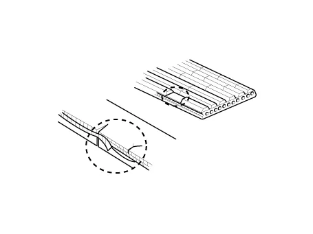
Visually check the belt for excessive wear, frayed cords etc.
If any defect has been found, replace the drive belt.
|

Drive Belt Tensioner. Repair procedures
| Removal and Installation |
|
| 1. |
Remove the drive belt.
(Refer to Drive Belt System - "Drive Belt")
|
| 2. |
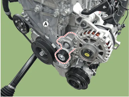
Remove the drive belt auto tensioner (A).
|
| 3. |
Install in the reverse order of removal.
|
Crankshaft Damper Pulley. Repair procedures
| Removal and Installation |
|
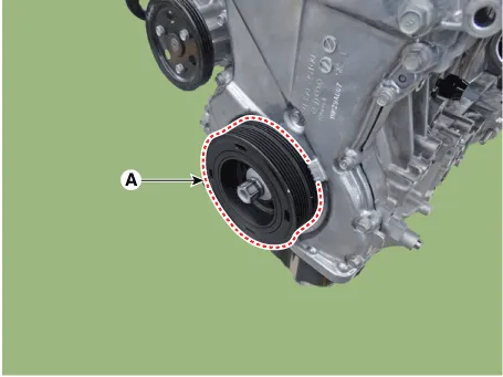
| 1. |
Remove the drive belt.
(Refer to Drive Belt System - "Drive Belt")
|
| 2. |
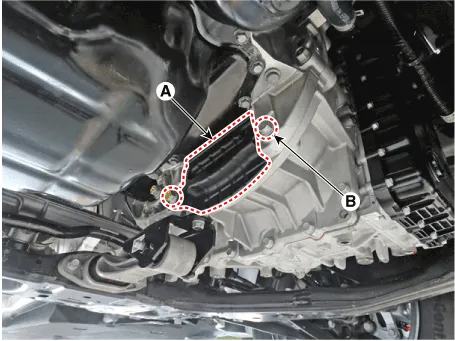
Remove the crankshaft damper pulley (A).
|

| 3. |
Install in the reverse order of removal.
|
Engine Cover. Repair procedures Removal and Installation 1. Remove the engine cover (A). • Remove the engine cover on room temperature.
Components and components location Components 1. Front oil seal 2. Timing chain cover 3. Timing chain 4. Cam to cam bracket 5.
Other information:
Hyundai Santa Fe (TM) 2019-2023 Service and Repair Manual: Electro Chromic Inside Rear View Mirror
Description and operation Description The ECM (Electro Chromatic inside rear view Mirror) is intended dim the reflecting light in the rear view mirror. The forward facing sensor detects brightness of the surroundings, while the rearward looking sensor is for the light from the rear.
Hyundai Santa Fe (TM) 2019-2023 Service and Repair Manual: Button Engine Start System
Description and operation Description System Overview The System offers the following features: – Changing the state of engine ignition and power by using the start button. – Controlling external relays for ACC / IGN1 / IGN2 terminal switching and STARTER, without use
Categories
- Manuals Home
- Hyundai Santa Fe Owners Manual
- Hyundai Santa Fe Service Manual
- LCD Display
- Rear Disc Brake. Repair procedures
- Horn
- New on site
- Most important about car
