Hyundai Santa Fe (TM): ESP(Electronic Stability Program) System / Description and operation
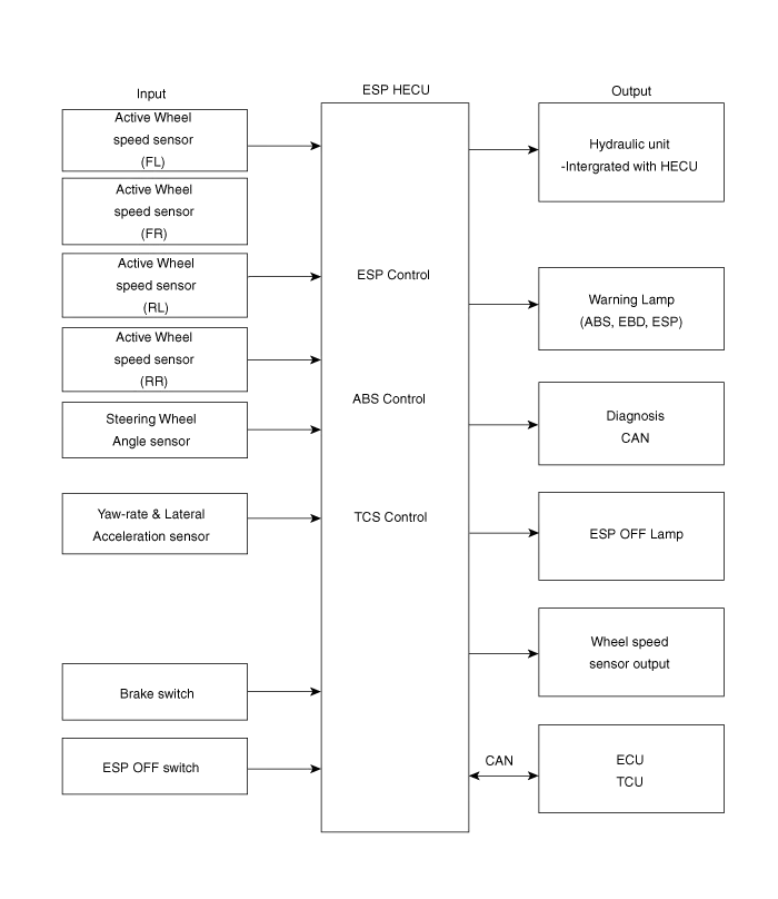
| Description of ESP |
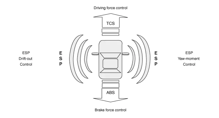
| ESP Operation Mode |
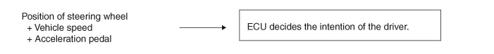
| 1. |
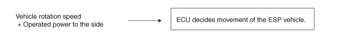
STEP 1
The ESP analyzes the intention of the driver.
|
| 2. |
STEP 2
It analyzes the movement of the ESP vehicle.
|
| 3. |
STEP 3
The HECU calculates the required strategy, then actuates the appropriate
valves and sents torque control requests via CAN to maintain vehicle
stability.
|
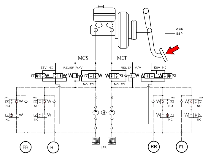
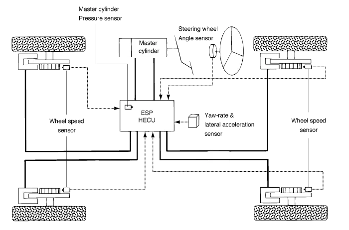
| ESP Hydraulic System Diagram |
| 1. |
ESP Non-operation : Normal braking.
|
| 2. |
ESP operation
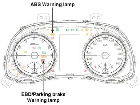
Warning Lamp Control
|
||||||||||||||||||||||
| – |
During the initialization phase after IGN ON. (continuously 3 seconds).
|
| – |
In the event of inhibition of ABS functions by failure.
|
| – |
During diagnostic mode.
|
| – |
When the ECU Connector is seperated from ECU.
|
| – |
Cluster lamp is ON when communication is impossible with CAN module.
|
| – |
During the initialization phase after IGN ON. (continuously 3 seconds).
|
| – |
When the Parking Brake Switch is ON or brake fluid level is low.
|
| – |
When the EBD function is out of order .
|
| – |
During diagnostic mode.
|
| – |
When the ECU Connector is seperated from ECU.
|
| – |
Cluster lamp is ON when communication is impossible with CAN module.
|
| – |
During the initialization phase after IGN ON. (continuously 3 seconds).
|
| – |
When the ESP function is inhibited by system failure.
|
| – |
When the ESP control is operating. (Blinking - 2Hz)
|
| – |
During diagnostic mode.(Except standard mode)
|
| – |
Cluster lamp is ON when communication is impossible with CAN module.
|
| – |
During the initialization mode after IGN ON. (continuously 3 seconds).
|
| – |
ESP Off lamp is On when driver input the ESP Off switch.
|
Components 1. ABS control module (HECU) 2. Front wheel speed sensor 3. Rear wheel speed sensor 4. ABS warning lamp 5.
Circuit Diagram ABS / ESC ESCi/ESCi+(EPB Integrated) Terminal Function ABS / ESC PIN No Desciption Current Resistance 1 Pump motor supply voltage 60 A 10 mΩ 2 - - - 3 - - - 4 C-CAN High 100 mA 250 mΩ 5 C-CAN Low 100 mA 250 mΩ 6 - - - 7 P-CAN Low 100 mA 250 MΩ 8 P-CAN High 100 mA 250 MΩ 9 Wheel speed sensor supply voltage (Left rear) 100 mA 250 MΩ 10 Wheel speed sensor supply voltage (Right rear) 100 mA 250 MΩ 11 Wheel speed sensor supply voltage (Right front) 100 mA 250 MΩ 12 Wheel speed sensor supply voltage (Left front) 100 mA 250 MΩ 13 Recycle pump ground 40 A 10 MΩ 14 - - - 15 Clutch stroke sensor signal 1.
Other information:
Hyundai Santa Fe (TM) 2019-2023 Service and Repair Manual: Components and components location
Component Location Index Engine Room 1. Service port (High pressure) 2. A/C pressure transducer (APT) 3. Service port (Low pressure) 4. Compressor 5. Suction & Liquid pipe assembly 6. Expansion valve Interior 1.
Hyundai Santa Fe (TM) 2019-2023 Service and Repair Manual: Surround View Monitor (SVM)
Description and operation Description Surround View Monitor (SVM) is the system that allows video monitoring of 360 degrees around the vehicle. The system includes 4 ultra optical camera mounted around the vehicle (front, both sides, rear).
Categories
- Manuals Home
- Hyundai Santa Fe Owners Manual
- Hyundai Santa Fe Service Manual
- Front Radar Unit. Repair procedures
- Restraint
- Hydraulic System
- New on site
- Most important about car
