Hyundai Santa Fe (TM): ESP(Electronic Stability Program) System / Schematic diagrams
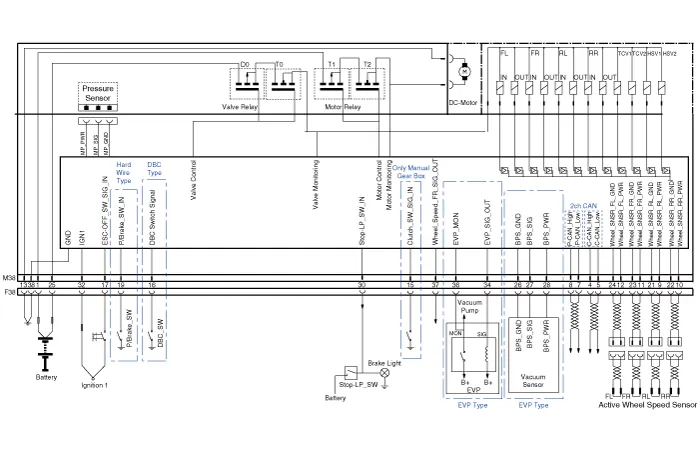
| Circuit Diagram |

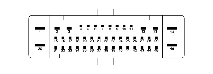
| Terminal Function |
|
PIN No |
Desciption |
Current |
Resistance |
|
1 |
Pump motor supply voltage |
60 A |
10 mΩ |
|
2 |
- |
- |
- |
|
3 |
- |
- |
- |
|
4 |
C-CAN High |
100 mA |
250 mΩ |
|
5 |
C-CAN Low |
100 mA |
250 mΩ |
|
6 |
- |
- |
- |
|
7 |
P-CAN Low |
100 mA |
250 MΩ |
|
8 |
P-CAN High |
100 mA |
250 MΩ |
|
9 |
Wheel speed sensor supply voltage (Left rear) |
100 mA |
250 MΩ |
|
10 |
Wheel speed sensor supply voltage (Right rear) |
100 mA |
250 MΩ |
|
11 |
Wheel speed sensor supply voltage (Right front) |
100 mA |
250 MΩ |
|
12 |
Wheel speed sensor supply voltage (Left front) |
100 mA |
250 MΩ |
|
13 |
Recycle pump ground |
40 A |
10 MΩ |
|
14 |
- |
- |
- |
|
15 |
Clutch stroke sensor signal |
1.2 mA |
250 MΩ |
|
16 |
DBC switch signal |
1.2 mA |
250 MΩ |
|
17 |
VDC OFF switch signal |
1.2 mA |
250 MΩ |
|
18 |
- |
- |
- |
|
19 |
Parking brake switch signal |
1.2 mA |
250 MΩ |
|
20 |
- |
- |
- |
|
21 |
Wheel speed sensor ground (Left rear) |
40 mA |
250 MΩ |
|
22 |
Wheel speed sensor ground (Right rear) |
40 mA |
250 MΩ |
|
23 |
Wheel speed sensor ground (Right front) |
40 mA |
250 MΩ |
|
24 |
Wheel speed sensor ground (Left front) |
40 mA |
250 MΩ |
|
25 |
Solenoid valve voltage |
30 A |
10 MΩ |
|
26 |
Brake pressure sensor ground |
60 mA |
10 MΩ |
|
27 |
Brake pressure sensor signal |
40 mA |
250 MΩ |
|
28 |
Brake pressure sensor power |
60 mA |
10 MΩ |
|
29 |
- |
- |
- |
|
30 |
Brake lamp switch |
1.2 mA |
250 MΩ |
|
31 |
- |
- |
- |
|
32 |
IGN 1 |
10 mA |
50 MΩ |
|
33 |
- |
- |
- |
|
34 |
Electronic vacuum pump output |
1 mA |
50 MΩ |
|
35 |
- |
- |
- |
|
36 |
Electronic vacuum pump motor monitor |
100 mA |
250 MΩ |
|
37 |
Wheel speed sensor output |
50 mA |
250 MΩ |
|
38 |
Solenoid valve ground |
30 A |
10 MΩ |
|
PIN No |
Desciption |
Current |
Resistance |
|
1 |
Pump motor supply voltage |
60 A |
10 MΩ |
|
2 |
Right rear EPB motor power |
15 A |
10 MΩ |
|
3 |
Right rear EPB motor ground |
15 A |
10 MΩ |
|
4 |
Brake pressure sensor ground |
60 mA |
10 MΩ |
|
5 |
- |
- |
- |
|
6 |
Electronic parking brake signal 1 [Connect] |
20 mA |
250 MΩ |
|
7 |
Electronic parking brake signal 2 [Connect] |
20 mA |
250 MΩ |
|
8 |
Electronic parking brake signal 3 [Release] |
20 mA |
250 MΩ |
|
9 |
Electronic parking brake signal 4 [Release] |
20 mA |
250 MΩ |
|
10 |
Brake pressure sensor signal |
40 mA |
250 MΩ |
|
11 |
Brake pressure sensor power |
60 mA |
10 MΩ |
|
12 |
Left rear EPB motor ground |
15 A |
10 MΩ |
|
13 |
Left rear EPB motor power |
15 A |
10 MΩ |
|
14 |
Solenoid valve ground |
40 A |
10 MΩ |
|
15 |
DBC switch signal |
1.2 mA |
250 MΩ |
|
16 |
- |
- |
- |
|
17 |
VDC OFF switch signal |
1.2 mA |
250 MΩ |
|
18 |
- |
- |
- |
|
19 |
C-CAN High |
100 mA |
250 MΩ |
|
20 |
C-CAN Low |
100 mA |
250 MΩ |
|
21 |
- |
|
|
|
22 |
P-CAN LOW |
100 mA |
250 MΩ |
|
23 |
P-CAN High |
100 mA |
250 MΩ |
|
24 |
- |
- |
- |
|
25 |
Wheel speed sensor supply voltage (Left rear) |
150 mA |
250 MΩ |
|
26 |
Wheel speed sensor supply voltage (Right rear) |
150 mA |
250 MΩ |
|
27 |
Wheel speed sensor supply voltage (Right front) |
150 mA |
250 MΩ |
|
28 |
Wheel speed sensor supply voltage (Left front) |
150 mA |
250 MΩ |
|
29 |
Electronic vacuum pump motor monitor |
100 mA |
250 MΩ |
|
30 |
Solenoid valve voltage |
40 A |
10 MΩ |
|
31 |
- |
- |
- |
|
32 |
- |
- |
- |
|
33 |
- |
- |
- |
|
34 |
Auto holding ON/OFF switch signal |
1.2 mA |
250 MΩ |
|
35 |
Brake lamp switch |
1.2 mA |
250 MΩ |
|
36 |
Electronic vacuum pump output |
1 A |
60 MΩ |
|
37 |
IGN 1 |
10 mA |
50 MΩ |
|
38 |
- |
- |
- |
|
39 |
- |
- |
- |
|
40 |
- |
- |
- |
|
41 |
Wheel speed sensor ground (Left rear) |
40 mA |
250 MΩ |
|
42 |
Wheel speed sensor ground (Right rear) |
40 mA |
250 MΩ |
|
43 |
Wheel speed sensor ground (Right front) |
40 mA |
250 MΩ |
|
44 |
Wheel speed sensor ground (Left front) |
40 mA |
250 MΩ |
|
45 |
Wheel speed sensor output (Right front) |
50 mA |
250 MΩ |
|
46 |
Recycle pump ground |
60 A |
10 MΩ |
Description of ESP ESP recognizes critical driving conditions, such as panic reactions in dangerous situations, and stabilizes the vehicle by wheel-individual braking and engine control intervention.
Failure Diagnosis 1. In principle, ESP and TCS controls are prohibited in case of ABS failure. 2.
Other information:
Hyundai Santa Fe (TM) 2019-2023 Service and Repair Manual: IMS (Integrated Memory)
Description and operation Description The optimal seat position set by the driver is memorized into the power seat unit by using IMS switch. In case of the position change, the seat can restore its preset position by IMS switch.
Hyundai Santa Fe (TM) 2019-2023 Service and Repair Manual: Specifications
Specification Air Conditioner Item Specification Compressor Type 7HVe17 Oil type & Capacity Single (Front only) FD46XG(IDMITSU) 100± 10cc (3.
Categories
- Manuals Home
- Hyundai Santa Fe Owners Manual
- Hyundai Santa Fe Service Manual
- Rear seats
- Engine Control/Fuel System
- Automatic Transaxle Control System
- New on site
- Most important about car
