Hyundai Santa Fe: Power Tailgate Module / Description and operation
Hyundai Santa Fe (TM) 2019-2025 Service Manual / Body Electrical System / Power Tailgate Module / Description and operation
| Description |
Power tailgate is an electro-mechanical system designed to provide power opening
and closing of the tailgate through the push of a button of a remote key (fob),
console switch, inner switch or an outside handle switch of the tailgate.
The power tailgate will reverse direction of travel if resistance to movement
is detected while the tailgate is being opened or closed.
Tailgate Position And Direction
The PTG system will measure the Tailgate position via an integrated hall sensor
inside the Spindle drive unit motor.
The moving direction of tailgate will be detected by analyzing the direction
of the drive unit motor.
The hall sensor pulse counting (position detection) is active during power and
manual operation mode.
System Components
| 1. |
PTG Unit
PTG unit is located in rear left luggage side trim.
PTG drive unit drive the two actuators (Spindles) by measuring the driving
motors.
PTG unit also controls anti trap functions by hall sensor analysis in
the anti-pinch strip.
|
| 2. |
PTG Latch Assembly
PTG latch assembly is consist of Power Latch (A) and Power Closeing
Unit (B).
Power latch is located in the lower part of tail gate panel.
|
| 3. |
PTG Spindle
PTG spindle open and close the tailgate by driving the motor.
|
| 4. |
Anti-Pinch Strip
During power closing or cinching, the PTG system shall reverse to full
open if an anti-pinch strip signal is received. However, the anti-pinch
strips will not work when the Tailgate is idle in the full closed, full
open, or stopped positions.
|
| 5. |
SMK (Smart key)
Push the power tailgate open of the SMK more than 0.5s to open the power
tailgate. Power Open operation shall be reversed when an additional
Open/Close signal is received during power opening.
|
| 6. |
Tailgate inner switch
|
| 7. |
Tailgate buzzer
When a power operation cannot be performed as requested or an obstacle
has been detected.
|
| Operation |
Power Tailgate Opening
** - Primary switch signal received by PTGM via CAN bus (sent by SJB)
PTGM Opening procedure:
| 1. |
Opening can be triggered after a signal is received from, driver-console
switch, outside handle switch, remote Key (FOB)
|
| 2. |
The latch will be released (by SJB) by actuation of latch motor.
|
| 3. |
On latch release, the tailgate latch pops out of the striker.
|
| 4. |
PTG module controls the tailgate motor in order to open the tailgate.
|
| 5. |
The rotating speed of the tailgate motor can be hall sensor that is
built in the motor.
|
| 6. |
Opening angle of the tailgate is calculated by counting the input pulse
signals from Hall sensor.
|

Power Tailgate Closing
PTGM Closing procedure:
| 1. |
Closing can be triggered after receiving a signal from, console (driver)
switch, ouside handle switch, remote key (FOB), inner switch
|
| 2. |
PTG module controls the tailgate motor in order to close the tailgate
|
| 3. |
Closing angle of the tailgate is calculated by counting the input pulse
signlas from hall sensor
|
| 4. |
The rotating speed of the tailgate motor can be hall sensor that is
built in the motor
|
| 5. |
The tailgate latch engages with the striker and the latch is locked
mechanically (Latch unlock → Latch lock)
|
| 6. |
PTGM stops the tailgate motor operation after detecting the tailgate
latch's secondary signal
|
| 7. |
On detecting the latch's secondary signal, the power close unit (PCU)
starts the contract (cinch) operation and stops after the latch lock
signal is detected
|
| 8. |
After contract operation is stopped, PCU is rewound until the PCU home
position is reached
|
| 9. |
The tailgate is completely closed and latch is fully locked
|
Learned/Calculated/Programmed positions
| 1. |
Maximum Point for Opening
Above this position a start in opening direction could make the tailgate
move beyond the Maximum Basic Position and overload the mechanical system
(hinges).
Therefore the start of an opening action above this point is disabled.
Anyway the tailgate moves beyond this point, if it has been started
at a lower position.
|
| 2. |
Learned Mechanical End Position
This is the mechanical block position while opening and is considered
to be 100% opening. During the first tailgate opening this position
is learned.
After learning, the tailgate will not move beyond the Maximum Basic
Position, which is defined by the Learned Mechanical Position – Security
Distance.
All positions are defined by parameters in the ECU or programmed by
the user (Basic Programmed Position)
|
Programming the max. T/gate opening (Garage Position)
| 1. |
The customizable Programmed Basic Position is set equal to the Maximum
Basic Position after the Learned Mechanical End Position is learned.
|
System Parameterization
Due to mechanical tolerances and adjustments in vehicle production and assembly
the power operated tailgate needs calibration of the maximum movement range
before proper operation can be ensured.
The tailgate’s maximum movement range is represented by the number of Hall-pulses
received by the ECU from the actuators’ speed / position sensors during a tailgate
movement from the fully closed position (closure unit in fully latched position)
to the upper end position limited by mechanical constraints (e.g. upper bump
stops, spindle length or similar).
Calibration Mode
Manual De-calibration Mode
Buzzer operation is defined in the following chart
|
|
BUZZER |
LAMP *) |
Remark |
|
T/gate start |
2 times |
2 times |
When T/gate is triggered by Remote Contol or T/gate Console Switch |
|
T/gate start |
n.a. |
n.a. |
When T/gate is triggered by T/gate Inner Switch or T/gate Outer Handle Switch |
|
T/gate stop |
n.a. |
n.a. |
|
|
System error |
3 Times |
- |
PCU/Tailgate antiplay active, 0ver-/undervoltage condition, Endposition-/position
error, spindle error, CAN error, Latch closed when Tailgate open |
|
T/gate not closed |
10 times |
10 times |
Latch Lock Switch not present |
|
During Calibration run |
Continuous ON-OFF beeping |
n.a. |
Activate buzzer but not C_PTHazard |
|
Max. End Position learned |
n.a. |
2 times |
Buzzer confirms learning finished |
|
Max. End Position deleted |
1 time |
n.a. |
Buzzer confirms "position deleted" |
|
Car is moving with open T/gate |
10 times |
n.a. |
T/gate open AND Speed >3km/h |
|
Garage Position saved |
2 times |
n.a. |
Buzzer confirms "New Garage Position" |
*) Lamp will be synchronized by sending C_PTHazard simultaneously to Buzzer
signal

 Components and components location
Component Location (1)
1. Buzzer
2. Console S/W
3. RKE
4. Anti Pinch Strip
5. Spindle Drive
6. Tailgate Trim Switch
7...
Other information:
Hyundai Santa Fe (TM) 2019-2025 Owner's Manual: Starting the engine
WARNING Always wear appropriate shoes when operating your vehicle. Unsuitable shoes, such as high heels, ski boots, sandals, flipflops, etc., may interfere with your ability to use the brake and accelerator pedals. Do not start the vehicle with the accelerator pedal depressed...
Hyundai Santa Fe (TM) 2019-2025 Service Manual: Shift Cable. Repair procedures
Removal 1. Make sure vehicle does not roll before setting shift lever to "N" position. 2. Turn ignition switch OFF and disconnect the negative (-) battery cable. 3...
Categories
- Manuals Home
- 4th Generation Santa Fe Owners Manual
- 4th Generation Santa Fe Service Manual
- Head-up display settings
- Seat cushion extension adjustment (for driver's seat)
- Brake bleeding procedures
- New on site
- Most important about car
Instrument panel overview
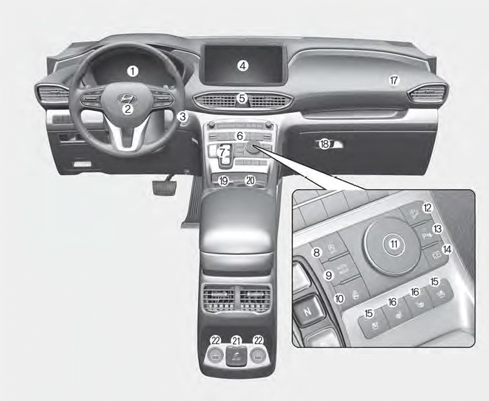
1. Instrument cluster
2. Driver’s front air bag
3. Engine Start/Stop button
4. Infotainment system
5. Hazard warning lamp switch
6. Climate control system
7. Shift button
8. ISG (Idle Stop and Go) button
9. Auto Hold button
10. Heated steering wheel button
11. Drive mode button
12. DBC (Downhill Brake Control) button
13. Parking Safety button
14. Parking/View button
15. Air ventilation seat button
16. Seat warmer
17. Passenger’s front air bag
18. Glove box
19. Wireless charging system pad
20. Cup holder
21. AC inverter
22. USB charger

Copyright © 2025 www.hsafe4.com