Hyundai Santa Fe: Air conditioning System / Compressor. Description and operation
Hyundai Santa Fe (TM) 2019-2025 Service Manual / Heating,Ventilation And Air Conditioning / Air conditioning System / Compressor. Description and operation
| Description |
The compressor is the power unit of the A/C system.
It is located on the side of engine block and driven by a V-belt of the engine.
The compressor changes low pressure and low temperature refrigerant gas into
high pressure and high temperature refrigerant gas.
Variable Swash Plate Compressor
The compressor has a swash plate that rotates to reciprocate pistons, which
compress refrigerant.
The variable swash plate compressor controls the swash plate angle to change
the refrigerant displacement. It achieves precise cooling capability control
in accordance with vehicle interior and driving conditions.
The internally controlled variable swash plate compressor changes the swash
plate angle by a MCV (Mechanical Control Valve) in accordance with fluctuation
of a suction pressure.
The externally controlled variable swash plate compressor changes the swash
plate angle by an ECV (Electric Control Valve) in accordance with an electrical
signal from the heater & A/C control unit.
This enables stable temperature control and improved driving sensation.
ECV Control Diagram
 Refrigerant Line. Repair procedures
Replacement
[Front suction & Liquid pipe assembly]
1.
If a compressor is available, the air conditioner is operated for a
few minutes in the engine idle state and then the engine is stopped...
 Compressor. Components and components location
Components
[Diesel 2.2 TCI-R]
1. Clutch Bolt
2. Disc & Hub Assembly
3. Clutch Spacer
4. Snap Ring
5. Pulley
6...
Other information:
Hyundai Santa Fe (TM) 2019-2025 Owner's Manual: Four wheel drive (4WD)
Four Wheel Drive (4WD) delivers engine power to front and rear wheels for maximum traction. 4WD is useful when extra traction is required, such as when driving on, muddy, wet, or snow-covered roads. WARNING To reduce the risk of SERIOUS INJURY or DEATH: Do not drive in conditions that exceed the vehicles intended design such as challenging off-road conditions...
Hyundai Santa Fe (TM) 2019-2025 Service Manual: Seat Belt Buckle Switch (BS). Repair procedures
Removal 1. Disconnect the battery negative cable, and wait for at least three minutes before beginning work. 2. Remove the front seat assembly. (Refer to Body - "Front Seat Assembly") 3...
Categories
- Manuals Home
- 4th Generation Santa Fe Owners Manual
- 4th Generation Santa Fe Service Manual
- Warning and indicator lights
- Troubleshooting
- Folding the rear seat
- New on site
- Most important about car
Interior Overview
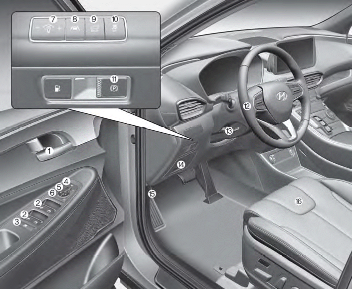
1. Inside door handle
2. Power window switches
3. Power window lock button/Electronic child safety lock button
4. Side view mirror folding button
5. Side view mirror control switch
6. Central door lock switch
7. Instrument panel illumination control switch

Copyright © 2025 www.hsafe4.com