Hyundai Santa Fe (TM): Automatic Transaxle System / Automatic Transaxle Fluid (ATF). Repair procedures
| Automatic Transaxle Fluid (ATF) Level Check |
|

| 1. |
Remove the air duct and air cleaner.
(Refer to Engine Mechanical System - "Air Cleaner")
|
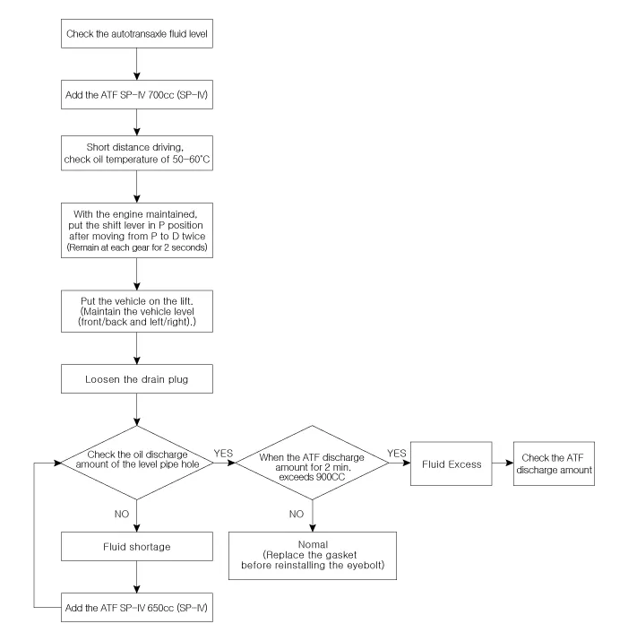
| 2. |
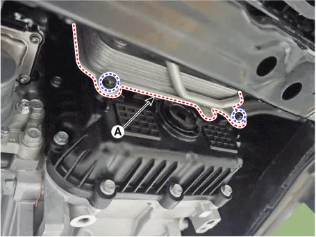
Remove the eyebolt (A).
|
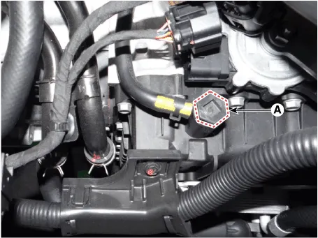
| 3. |
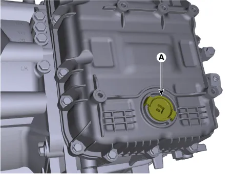
Add ATF SP-IV 700cc to the ATF injection hole (A).
|
| 4. |
Start the engine.
(Don’t step on brake and accelerator simultaneously.)
|
| 5. |
Confirm that the temperature of the automatic transaxle oil temperature
sensor is 50 - 60°C (122 - 140°F) with the diagnostic tool.
|
| 6. |
Shift the select lever slowly from “P” to “D”, then “D” to “P” and repeat
one more at idle.
|
| 7. |
Raise the vehicle, and make sure it is securely supported.
|
| 8. |
Remove the engine room under cover.
(Refer to Engine Mechanical System - "Engine Room Under Cover")
|
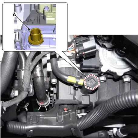
| 9. |
In case by ATF warmer, loosening the mounting bolts and then separate
the ATF warmer (A).
|
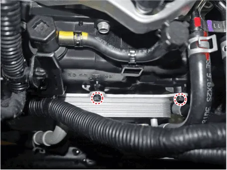
| 10. |
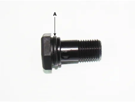
Remove the ATF level check plug (A) from the valve body cover.
|
| 11. |
If the ATF flows out of the overflow plug in thin steady stream, the
ATF level is correct.
Then finish the procedure and tighten the ATF level check plug.
|

| 12. |
Remove the engine room under cover.
(Refer to Engine Mechanical System - "Engine Room Under Cover")
|
| 13. |
Put down the vehicle with the lift and then tighten the eyebolt (A).
|
| Replacement |
ATF of 8 speed automatic transaxle doesn’t be replaced. But, if the
vehicle is severe use or business use, replace ATF every 60,000 miles
for severe usage.
Severe usage is defined as
|
|
| 1. |
Remove the air duct and air cleaner assembly.
(Refer to Engine Mechanical System - "Air Cleaner")
|
| 2. |
Remove the engine room under cover.
(Refer to Engine Mechanical System - "Engine Room Under Cover")
|
| 3. |
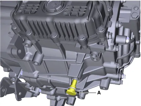
Remove the drain plug (A) and reinstall the drain plug after draining
ATF totally.
|
| 4. |
Put down the vehicle with the lift and then remove the eyebolt (A).
|
| 5. |
Add ATF SP-IV 700cc to the ATF injection hole (A).
|
| 6. |
Check the ATF level.
(Refer to Automatic Transaxle System - "Automatic Transaxle Fluid (ATF)")
|
| 7. |
Then finish check the ATF level procedure and install the under cover.
(Refer to Engine Mechanical System - "Engine Room Under Cover")
|
| 8. |
Put down the vehicle with the lift and then tighten the eyebolt (A).
|
Components Location 1. ATF Injection plug (Eyebolt) 2. ATF injection plug gasket 3. ATF level check plug 4.
Other information:
Hyundai Santa Fe (TM) 2019-2023 Service and Repair Manual: Mode Control Actuator. Repair procedures
Inspection 1. Turn the ignition switch OFF. 2. Disconnect the mode control actuator connector. 3. Verify that the mode control actuator operates to the defrost mode when connecting 12V to terminal 3 and grounding terminal 7.
Hyundai Santa Fe (TM) 2019-2023 Service and Repair Manual: Special service tools
Special Service Tools Tool Name / Number Illustration Description LKA Compensator (09890-3V100) Used for compensating front view camera unit Vertical measuring instrument (09964-C1200) Used to measure l
Categories
- Manuals Home
- Hyundai Santa Fe Owners Manual
- Hyundai Santa Fe Service Manual
- Convenience features
- Vehicle Information, Consumer Information and Reporting Safety Defects
- Electronic Parking Brake (EPB) warning light. AUTO HOLD indicator light
- New on site
- Most important about car
