Hyundai Santa Fe (TM): Automatic Transaxle System (SBC) / Automatic Transaxle System
Automatic Transaxle. Repair procedures
| Removal |
|

| 1. |
Turn ignition switch OFF and disconnect the negative (-) battery cable.
|
| 2. |
Remove the air cleaner assembly and air duct.
(Refer to Engine Mechanical System - "Air Cleaner")
|
| 3. |
Remove the battery and battery tray.
(Refer to Engine Electrical System - "Battery")
|
| 4. |
Loosen the bolts (B) and nut (A) and then separate the shift cable and
cable bracket (C) at the same time.
|
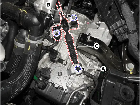
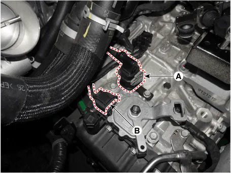
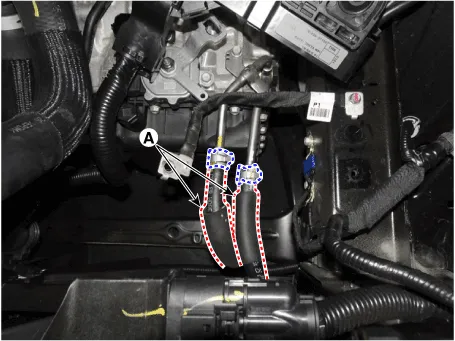
| 5. |
Dissconnect the main connector (A) and the position switch connector
(B).
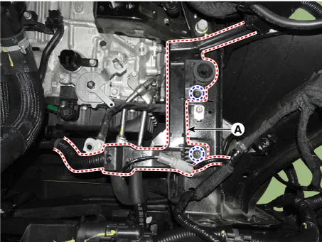
|
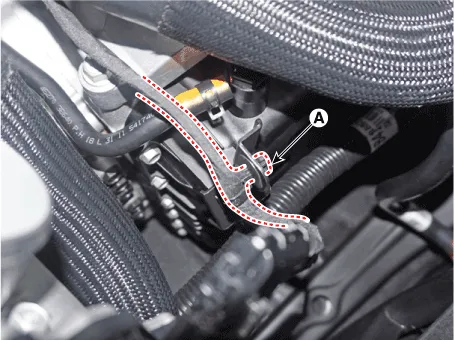
| 6. |
Separate the wiring clips (A).
|

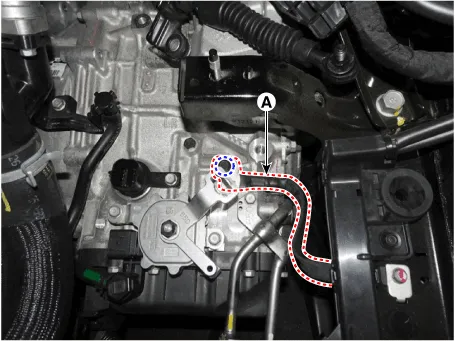
| 7. |
Remove the ground line (A).
|
| 8. |
Loosen the bolts and then separate the engine wiring (A).
|
| 9. |
Separate the ATF cooler hose (A).
|
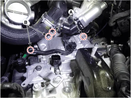
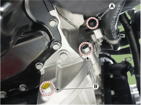
| 10. |
Loosen the transaxle upper mounting bolts (A) and the starter mounting
bolts (B).
|
| 11. |
Assemble the engine support fixture use a service special tools .(Beam
SST No.: 09200 - 3N000 Adapter SST No.: 09200-2W000, Engine fixture
adapter (rear) SST No.: 09200-L1100, Engine fixture adapter (front)
SST No.: 09200-L1200)
|
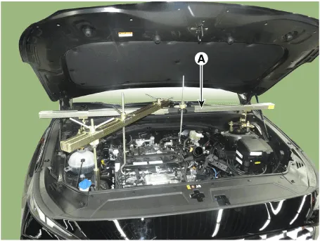
| 12. |
Using the engine support fixture (A), hold the engine and transaxle
assembly safely.
|
| 13. |
Remove the front wheel guard. [LH]
(Refer to Body (Interior and Exterior) - "Front Wheel Guard")
|
| 14. |
Loosen the transaxle bracket support mounting bolts (A).
|
| 15. |
Loosen the bolts and then removing the transaxle bracket (A).
|
| 16. |
Remove the under cover.
(Refer to Engine Mechanical System - "Engine Room Under Cover")
|
| 17. |
Remove the sub frame.
(Refer to Suspension System - "Sub Frame")
|
| 18. |
Remove the driveshaft assembly.
(Refer to Driveshaft and Axle - "Front Driveshaft")
|
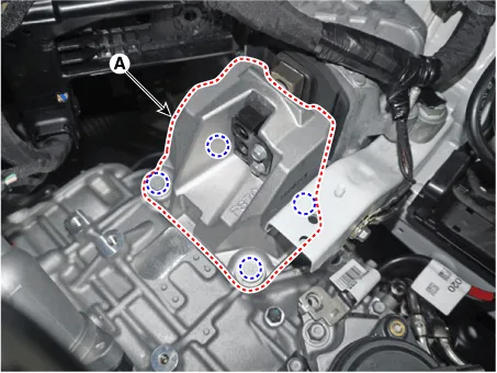
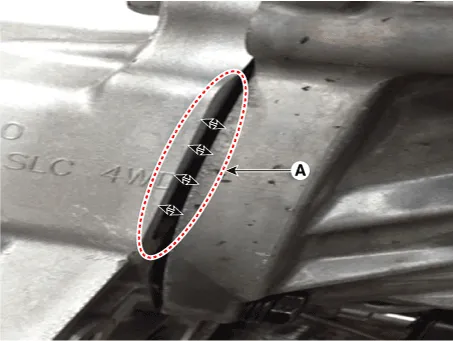
| 19. |
Loosen the bolts and then removing the roll rod support bracket (A).
|
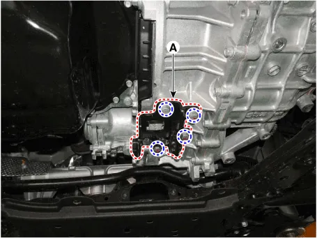
| 20. |
Remove the dust cover (A).
|
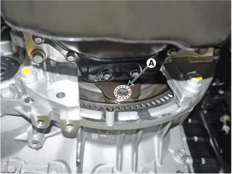
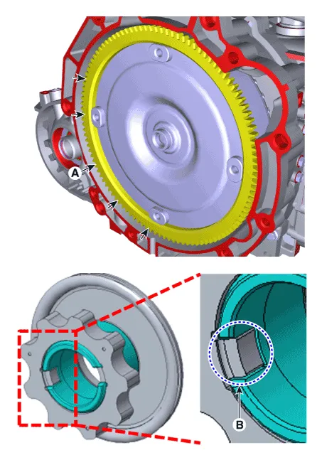
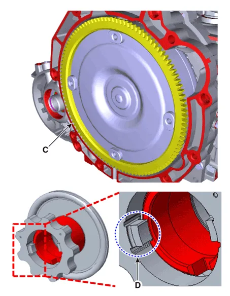
| 21. |
Loosen the mounting bolts (A) of the torque converter with rotating
the crankshaft.
|
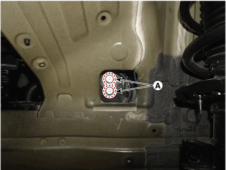
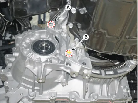
| 22. |
Remove the automatic transaxle with a jack after loonsening the mounting
bolts (A, B).
|
| Installation |
| 1. |
To install, reverse the removal procedure.
|

| 2. |
In case of the reinstallation.
|
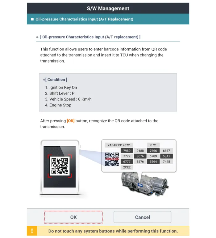
| 3. |
In case of the replacing with a new automatic transaxle.
|
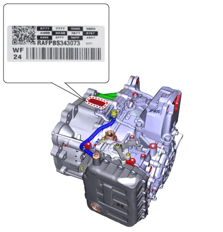

Automatic Transaxle Fluid (ATF). Components and components location
| Components Location |
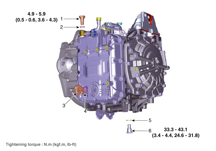
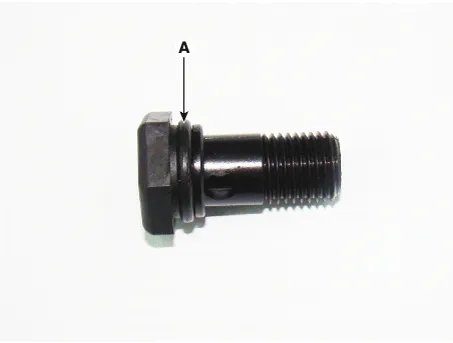
| 1. ATF Injection
plug (Eyebolt) 2. ATF injection plug gasket 3. ATF level check plug |
4. ATF level
check plug gasket 5. Drain plug gasket 6. Drain plug |
Automatic Transaxle Fluid (ATF). Repair procedures
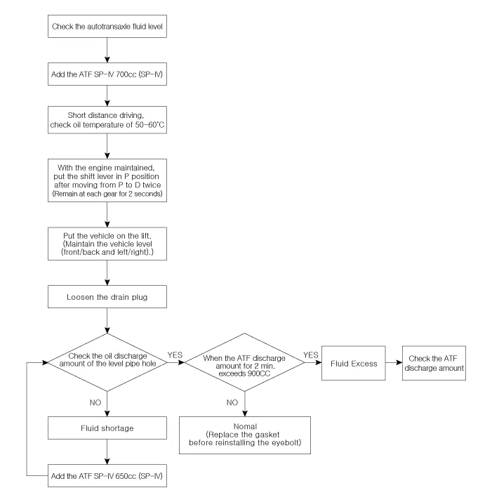
| Automatic Transaxle Fluid (ATF) Level Check |
|
| 1. |
Remove the air duct and air cleaner.
(Refer to Engine Mechanical System - "Air Cleaner")
|
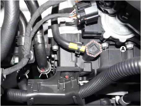
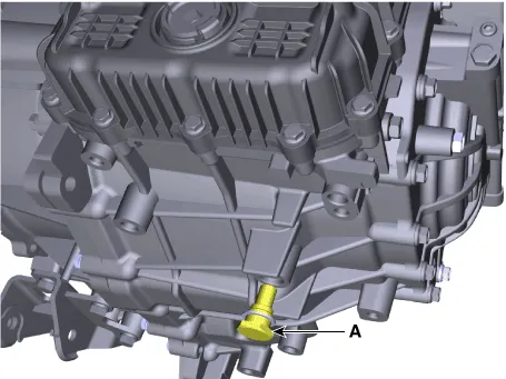
| 2. |
Remove the eyebolt (A).
|
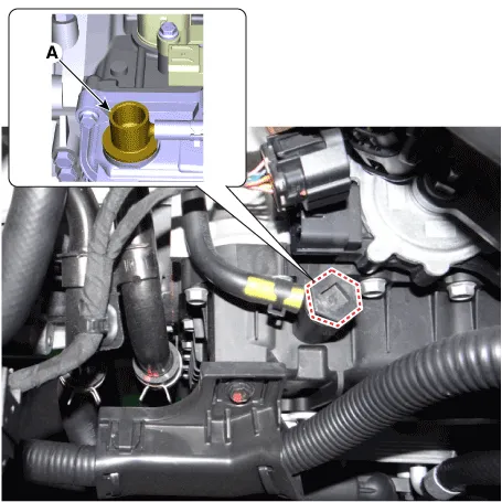
| 3. |
Add ATF SP-IV 700cc to the ATF injection hole (A).
|
| 4. |
Start the engine.
(Don’t step on brake and accelerator simultaneously.)
|
| 5. |
Confirm that the temperature of the automatic transaxle oil temperature
sensor is 50 - 60°C (122 - 140°F) with the diagnostic tool.
|
| 6. |
Shift the select lever slowly from “P” to “D”, then “D” to “P” and repeat
one more at idle.
|
| 7. |
Raise the vehicle, and make sure it is securely supported.
|
| 8. |
Remove the engine room under cover.
(Refer to Engine Mechanical System - "Engine Room Under Cover")
|
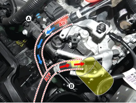
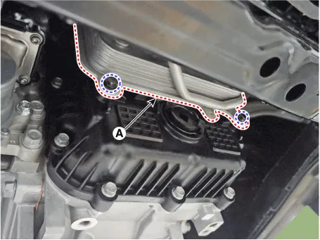
| 9. |
In case by ATF warmer, loosening the mounting bolts and then separate
the ATF warmer (A).
|

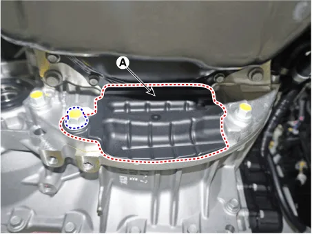
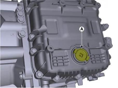
| 10. |
Remove the ATF level check plug (A) from the valve body cover.
|
| 11. |
If the ATF flows out of the overflow plug in thin steady stream, the
ATF level is correct.
Then finish the procedure and tighten the ATF level check plug.
|
| 12. |
Remove the engine room under cover.
(Refer to Engine Mechanical System - "Engine Room Under Cover")
|
| 13. |
Put down the vehicle with the lift and then tighten the eyebolt (A).
|
| Replacement |
ATF of 8 speed automatic transaxle doesn’t be replaced. But, if the
vehicle is severe use or business use, replace ATF every 60,000 miles
for severe usage.
Severe usage is defined as
|
|
| 1. |
Remove the air duct and air cleaner assembly.
(Refer to Engine Mechanical System - "Air Cleaner")
|
| 2. |
Remove the engine room under cover.
(Refer to Engine Mechanical System - "Engine Room Under Cover")
|
| 3. |
Remove the drain plug (A) and reinstall the drain plug after draining
ATF totally.
|
| 4. |
Put down the vehicle with the lift and then remove the eyebolt (A).
|
| 5. |
Add ATF SP-IV 700cc to the ATF injection hole (A).
|
| 6. |
Check the ATF level.
(Refer to Automatic Transaxle System - "Automatic Transaxle Fluid (ATF)")
|
| 7. |
Then finish check the ATF level procedure and install the under cover.
(Refer to Engine Mechanical System - "Engine Room Under Cover")
|
| 8. |
Put down the vehicle with the lift and then tighten the eyebolt (A).
|
Special Service Tools Tool (Number and Name) Illustration Use 09200-3N000 Engine support fixture (Beam) Removal and installation of the transaxle.
Other information:
Hyundai Santa Fe (TM) 2019-2023 Service and Repair Manual: Specifications
Specification Air Conditioner Item Specification Compressor Type 7HVe17 Oil type & Capacity Single (Front only) FD46XG(IDMITSU) 100± 10cc (3.
Hyundai Santa Fe (TM) 2019-2023 Service and Repair Manual: Compressor oil. Repair procedures
Oil Specification 1. The R-134a or R-1234yf system requires synthetic (PAG) compressor oil whereas the R-12 system requires mineral compressor oil. The two oils must never be mixed. 2.
Categories
- Manuals Home
- Hyundai Santa Fe Owners Manual
- Hyundai Santa Fe Service Manual
- Rear seats
- Auto Hold. Warning messages
- Instrument cluster
- New on site
- Most important about car
