Hyundai Santa Fe (TM): Automatic Transaxle Control System / Transaxle Oil Temperature Sensor. Repair procedures
| Inspection |
|

| Removal |
|

| 1. |
Turn ignition switch OFF and disconnect the negative (-) battery cable.
|
| 2. |
Remove the battery.
(Refer to Engine Electrical System - "Battery")
|
| 3. |
Remove the air cleaner assembly and air duct.
(Refer to Engine Mechanical System - "Air Cleaner")
|
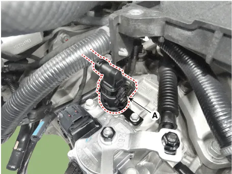
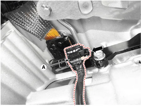
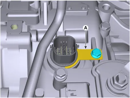
| 4. |
Disconnect the solenoid valve connector (A).
|
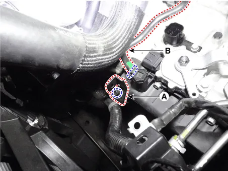
| 5. |
Loosen the bolt and then removing the wiring bracket (A).
|
| 6. |
Separate the air bleeder hose (B).
|
| 7. |
Remove the under cover.
(Refer to Engine Mechanical System - "Engine Room Under Cover")
|
| 8. |
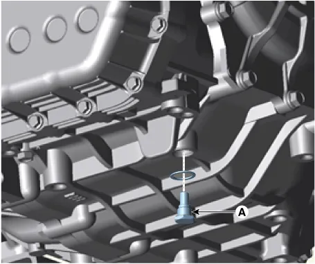
Remove the drain plug (A) and drain the ATF totally and then reinstall
the drain plug.
|
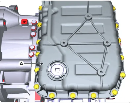
| 9. |
Loosen the mounting bolts (A) of the valve body cover.
|
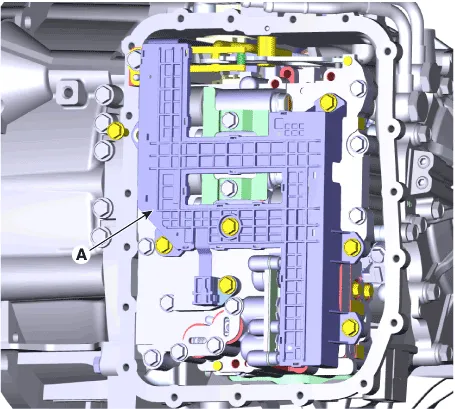
| 10. |
Loosen the bolts and then removing the main harness (A).
|
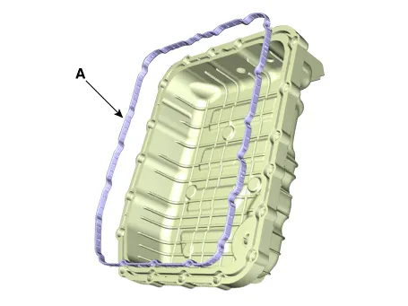
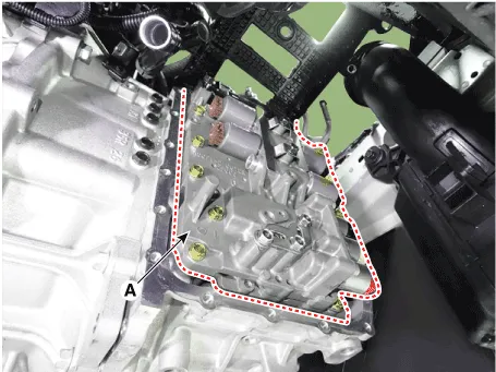
| 11. |
Loosen the mounting bolts and then removing the valve body assembly
(A).
|
| 12. |
Disconnect the input & output speed sensor connector (A).
|
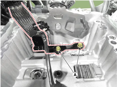
| 13. |
Loosen the main connector bolts (A).
|
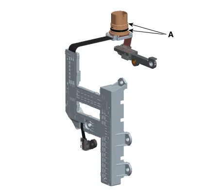
| 14. |
Remove the solenoid valve connector mounting clip (A).
|
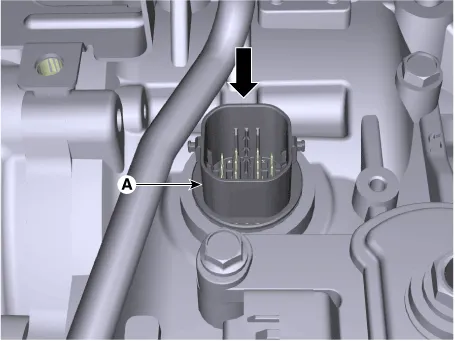
| 15. |
Remove the solenoid valve connector (A) by pushing down from the transaxle.
|
| Installation |
| 1. |
To install, reverse the removal procedure.
|
| 2. |
Check fluid level, after filling the automatic transaxle with fluid.
(Refer to Automatic Transaxle Syatem - "Automatic Transaxle Fluid(ATF)")
|
Specifications ▷ Type : Negative Thermal Coefficient Type Temp.[(°C)°F] Resistance (Ω) Min Max (-40) -40 48153 45301 51006 (-20) -4.
Description Input speed sensor is a vital unit that measures the rate of rotation of the input shaft inside the transaxle and delivers the readings to the TCM.
Other information:
Hyundai Santa Fe (TM) 2019-2023 Service and Repair Manual: Wireless Power Charger System
Description and operating principle Description and Operation Wireless Power Charger System During ACC or IG ON, battery voltage is supplied to the wireless power charger system to transmit an output of 5 W to mobile phone. Mobile phones certified with the wireless charging standard WPC (Qi 1.
Hyundai Santa Fe (TM) 2019-2023 Service and Repair Manual: Compressor. Components and components location
Components [Diesel 2.2 TCI-R] 1. Clutch Bolt 2. Disc & Hub Assembly 3. Clutch Spacer 4. Snap Ring 5. Pulley 6. Magnetic Coil Assembly 7. Compressor 8. Electric Control Valve (ECV) spacer 9.
Categories
- Manuals Home
- Hyundai Santa Fe Owners Manual
- Hyundai Santa Fe Service Manual
- Front Radar Unit. Repair procedures
- Battery. Specifications
- Engine Control/Fuel System
- New on site
- Most important about car
