Hyundai Santa Fe (TM): Automatic Transaxle Control System / Transaxle Control Module (TCM). Schematic diagrams
| TCM Connector and Terminal Function |
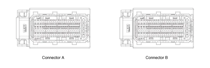
| TCM Terminal Function |
|
Pin No |
Description |
Connected to |
|
1 |
Power ground |
Chassis Ground |
|
2 |
- |
- |
|
3 |
- |
- |
|
4 |
- |
- |
|
5 |
- |
- |
|
6 |
Fuel Sender Signal |
Fuel Sender |
|
7 |
- |
- |
|
8 |
- |
- |
|
9 |
- |
- |
|
10 |
- |
- |
|
11 |
- |
- |
|
12 |
- |
- |
|
13 |
- |
- |
|
14 |
- |
- |
|
15 |
Stop Lamp Signal |
Stop Lamp |
|
16 |
Brake Test Switch |
Brake Switch |
|
17 |
|
|
|
18 |
- |
|
|
19 |
- |
|
|
20 |
Output Speed (Supply) |
ATM Solenoid Valve (Otput Speed) |
|
21 |
Input Speed (Supply) |
ATM Solenoid Valve (Input Speed) |
|
22 |
- |
- |
|
23 |
- |
- |
|
24 |
- |
- |
|
25 |
- |
- |
|
26 |
- |
- |
|
27 |
[A/T] SOL. (PWR1) |
ATM Solenoid Valve |
|
28 |
- |
- |
|
29 |
- |
- |
|
30 |
- |
- |
|
31 |
- |
- |
|
- |
- |
|
|
32 |
- |
- |
|
33 |
- |
- |
|
34 |
- |
- |
|
35 |
- |
- |
|
36 |
- |
- |
|
37 |
- |
- |
|
38 |
APT (Signal) |
A/C Pressure Transducer (APT) |
|
39 |
- |
- |
|
40 |
- |
- |
|
41 |
- |
- |
|
42 |
- |
- |
|
43 |
[A/T] Output Speed (Signal) |
Engine Control Relay |
|
44 |
[A/T] Input Speed (Signal) |
ATM Solenoid Valve |
|
45 |
- |
- |
|
46 |
- |
- |
|
47 |
- |
- |
|
48 |
[A/T] SOL. (VFS_26B) |
ATM Solenoid Valve |
|
49 |
[A/T] SOL. (VFS_OD) |
ATM Solenoid Valve |
|
50 |
[A/T] SOL. (VFS_PWR2) |
ATM Solenoid Valve |
|
51 |
- |
- |
|
52 |
- |
- |
|
53 |
- |
- |
|
54 |
- |
- |
|
55 |
- |
- |
|
56 |
APS (APS. 2 Ground) |
Accelerator Position Sensor (APS) |
|
57 |
APS (APS. 1 Ground) |
Accelerator Position Sensor (APS) |
|
58 |
- |
- |
|
59 |
- |
- |
|
60 |
- |
- |
|
61 |
APT (Ground) |
A/C Pressure Transducer (APT) |
|
62 |
- |
- |
|
63 |
- |
- |
|
64 |
- |
- |
|
65 |
- |
- |
|
66 |
- |
- |
|
67 |
- |
- |
|
68 |
- |
- |
|
69 |
[A/T] SOL. (OTS (-)) |
ATM Solenoid Valve |
|
70 |
[A/T] SOL. (OTS (+)) |
ATM Solenoid Valve |
|
71 |
- |
- |
|
72 |
[A/T] SOL. (VFS_LINE) |
ATM Solenoid Valve |
|
73 |
[A/T] SOL. (VFS_UD) |
ATM Solenoid Valve |
|
74 |
Start Relay Control |
B/Alarm Relay |
|
75 |
- |
- |
|
76 |
Vehicle Speed Signal |
IBU & ESP Control Module |
|
77 |
- |
- |
|
78 |
- |
- |
|
79 |
APS (APS. 2 Ground) |
Accelerator Position Sensor (APS) |
|
80 |
APS (APS. 1 Ground) |
Accelerator Position Sensor (APS) |
|
81 |
- |
- |
|
82 |
O2 Sensor (Up) (V_N) |
Oxygen Sensor (Up) |
|
83 |
O2 Sensor (Down) (Ground) |
Oxygen Sensor (Down) |
|
84 |
O2 Sensor (Up) (V_RC) |
Oxygen Sensor (Up) |
|
85 |
- |
- |
|
86 |
- |
- |
|
87 |
- |
- |
|
88 |
- |
- |
|
89 |
- |
- |
|
90 |
- |
- |
|
91 |
- |
- |
|
92 |
- |
- |
|
93 |
- |
- |
|
94 |
[A/T] SOL. Power (SS-B) |
ATM Solenoid Valve |
|
95 |
[A/T] SOL. (VFS_35R) |
ATM Solenoid Valve |
|
96 |
Memory Power |
PCB Block |
|
97 |
Wiper 'P' Input |
PCB Block |
|
98 |
- |
- |
|
99 |
- |
- |
|
100 |
- |
- |
|
101 |
- |
- |
|
102 |
APS (APS. 2 Supply) |
Accelerator Position Sensor (APS) |
|
103 |
APS (APS. 1 Supply) |
Accelerator Position Sensor (APS) |
|
104 |
APT (Supply) |
A/C Pressure Transducer (APT) |
|
105 |
O2 Sensor (Up) (V_G) |
Oxygen Sensor (Up) |
|
106 |
O2 Sensor (Down) (Signal) |
Oxygen Sensor (Down) |
|
107 |
O2 Sensor (Up) (V_IP) |
Oxygen Sensor (Up) |
|
108 |
- |
- |
|
109 |
Knock Sensor (Ground) |
Knock Sensor (KS) |
|
110 |
Knock Sensor (Signal) |
Knock Sensor (KS) |
|
111 |
- |
- |
|
112 |
- |
- |
|
113 |
- |
- |
|
114 |
- |
- |
|
115 |
- |
- |
|
116 |
- |
- |
|
117 |
[A/T] SOL. (SS-A) |
ATM Solenoid Valve |
|
118 |
[A/T] SOL. (VFS_T/CON) |
ATM Solenoid Valve |
|
119 |
Memory Power |
PCB Block |
|
Pin No |
Description |
Connected to |
|
1 |
Engine Control Relay 'ON' Input |
Engine Control Relay |
|
2 |
Engine Control Relay 'ON' Input |
Engine Control Relay |
|
3 |
Ground |
Ground |
|
4 |
Ground |
Ground |
|
5 |
Engine Control Relay 'ON' Input |
PCB Block |
|
6 |
P-CAN (High) |
P-CAN (High) |
|
7 |
P-CAN (Low) |
P-CAN (Low) |
|
8 |
- |
- |
|
9 |
- |
- |
|
10 |
- |
- |
|
11 |
- |
- |
|
12 |
- |
- |
|
13 |
OPTS (Signal) |
Oil Pressure Switch |
|
14 |
CMP (IN) (Signal) |
Camshaft Position Sensor (Intake) |
|
15 |
CMP (EX) (Signal) |
Camshaft Position Sensor (Exhaust) |
|
16 |
ETC Motor & Throttle Position Sensor.1 Signal |
ETC Motor & Throttle Position Sensor |
|
17 |
ETC Motor & Throttle Position Sensor Supply |
ETC Motor & Throttle Position Sensor |
|
18 |
- |
- |
|
19 |
- |
- |
|
20 |
- |
- |
|
21 |
- |
- |
|
22 |
- |
- |
|
23 |
- |
- |
|
24 |
Ignition Coil #1 (Control) |
Ignition Coil #1 |
|
25 |
O2 Sensor (Up) (Heater) |
Oxygen Sensor (Up) |
|
26 |
O2 Sensor (Down) (Heater) |
Oxygen Sensor (Down) |
|
27 |
- |
- |
|
28 |
- |
- |
|
29 |
Local-CAN (High) |
Electronic ATM Shift Lever, SCU (High) |
|
30 |
Local-CAN (Low) |
Electronic ATM Shift Lever, SCU (Low) |
|
31 |
- |
- |
|
32 |
- |
- |
|
33 |
- |
- |
|
34 |
WTS #1 (Signal) |
Engine Coolant Temperature Sensor |
|
35 |
Sensor Power : Map, CMP (In), CKP |
Sensor Power : Map, CMP (In), CKP |
|
36 |
- |
- |
|
37 |
CMP (In) (Ground) |
Camshaft Position Sensor (Intake) |
|
38 |
CMP (EX) (Ground) |
Camshaft Position Sensor (Exhaust) |
|
39 |
ETC Motor & Throttle Position Sensor.2 Signal |
ETC Motor & Throttle Position Sensor |
|
40 |
- |
- |
|
41 |
- |
- |
|
42 |
Fuel Pump Relay Control |
Fuel Pump Relay |
|
43 |
Engine Control Relay Control |
Engine Control Relay |
|
44 |
- |
- |
|
45 |
- |
- |
|
46 |
A/C Relay Control |
A/C Relay |
|
47 |
Ignition Coil #3 (Control) |
Ignition Coil #3 |
|
48 |
ETC DC Motor (+) |
ETC Motor |
|
49 |
ETC DC Motor (-) |
ETC Motor |
|
50 |
- |
- |
|
51 |
ON/Start (Input) |
ON/Start (Input) |
|
52 |
- |
- |
|
53 |
- |
- |
|
54 |
- |
- |
|
55 |
- |
- |
|
56 |
- |
- |
|
57 |
WTS #1 (Ground) |
Engine Coolant Temperature Sensor |
|
58 |
MAP & IAT Ground |
MAP Sensor |
|
59 |
- |
- |
|
60 |
- |
- |
|
61 |
- |
- |
|
62 |
ETC (TPS Groud) |
ETC Motor & Throttle Position Sensor |
|
63 |
- |
- |
|
64 |
- |
- |
|
65 |
Start Relay (Low Side) |
Start Relay |
|
66 |
- |
- |
|
67 |
- |
- |
|
68 |
- |
- |
|
69 |
- |
- |
|
70 |
OCV Control (EX) |
CVVT Oil Control Valve (OCV) |
|
71 |
OCV Control (IN) |
CVVT Oil Control Valve (OCV) |
|
72 |
- |
- |
|
73 |
- |
- |
|
74 |
- |
- |
|
75 |
Local-CAN2 (High) |
Can Check |
|
76 |
Local-CAN2 (Low) |
Can Check |
|
77 |
Alternator (IN) |
Alternator |
|
78 |
- |
- |
|
79 |
- |
- |
|
80 |
CKP (Ground) |
Crankshaft Position Sensor (CKPS) |
|
81 |
MAP Sensor (Signal) |
MAP Sensor |
|
82 |
Ignition Coil #1/#4 (Feedback) |
Ignition Coil #1 / #4 (Feedback) |
|
83 |
- |
- |
|
84 |
- |
- |
|
85 |
- |
- |
|
86 |
- |
- |
|
87 |
- |
- |
|
88 |
C/FAN Motor (PWM Signal) |
C/FAN Motor |
|
89 |
PCSV Control |
Purge Control Solanoid Valve |
|
90 |
CCV Control (Not Used) |
Canister Close Valve |
|
91 |
- |
- |
|
92 |
VIS Control |
Variable Intake Solenoid Valve (VIS) |
|
93 |
Ignition Coil #4 Control |
Ignition Coil #4 |
|
94 |
Injector Coil #4 Control |
Injector Coil #4 |
|
95 |
- |
- |
|
96 |
- |
- |
|
97 |
- |
- |
|
98 |
- |
- |
|
99 |
IMMO. Data Line |
Immobilizer |
|
100 |
- |
- |
|
101 |
- |
- |
|
102 |
- |
- |
|
103 |
Crankshaft Position Sensor (CKPS) signal input |
Crankshaft Position Sensor (CKPS) |
|
104 |
IAT Sensor |
MAP Sensor |
|
105 |
Ignition Coil #2 / #3 (Feedback) |
Ignition Coil #2 / #3 (Feedback) |
|
106 |
- |
- |
|
107 |
- |
- |
|
108 |
CMP (EX) (Supply) |
Camshaft Position Sensor (CMPS) |
|
109 |
FTPS (Not Used) |
Fuel Tank Pressure Sensor (FTPS) |
|
110 |
Engine RPM Signal |
Engine RPM Signal |
|
111 |
- |
- |
|
112 |
- |
- |
|
113 |
- |
- |
|
114 |
- |
- |
|
115 |
Thermostat PWM |
Electronic Thermostat |
|
116 |
Ignition Coil #2 Control |
Ignition Coil #2 |
|
117 |
Injector Coil #1 Control |
Injector Coil #1 |
|
118 |
Injector Coil #3 Control |
Injector Coil #3 |
|
119 |
Injector Coil #2 Control |
Injector Coil #2 |
Description • Monitoring the vehicle's operating conditions to determine the optimal gear setting. • Performing a gear change if the current gear setting differs from the identified optimal gear setting.
Inspection 1. TCM ground circuit test : Measure the resistance between TCM and chassis ground. (Inspect the terminal connected to the chassis ground with the back of harness connector as the inspection point of TCM side.
Other information:
Hyundai Santa Fe (TM) 2019-2023 Service and Repair Manual: Troubleshooting
Troubleshooting Problem Symptoms Table Before replacing or repairing air conditioning components, first determine if the malfunction is due to the refrigerant charge, air flow or compressor. Use the table below to help you find the cause of the problem.
Hyundai Santa Fe (TM) 2019-2023 Service and Repair Manual: Refrigerant Line. Repair procedures
Replacement [Front suction & Liquid pipe assembly] 1. If a compressor is available, the air conditioner is operated for a few minutes in the engine idle state and then the engine is stopped. 2.
Categories
- Manuals Home
- Hyundai Santa Fe Owners Manual
- Hyundai Santa Fe Service Manual
- Automatic Transaxle System (SBC)
- 4 Wheel Drive (4WD) System
- Auto Hold. Warning messages
- New on site
- Most important about car
