Hyundai Santa Fe (TM): Engine Control System / Variable Force Solenoid (VFS). Repair procedures
Hyundai Santa Fe (TM) 2019-2023 Service and Repair Manual / Engine Control/Fuel System / Engine Control System / Variable Force Solenoid (VFS). Repair procedures
| Inspection |
| 1. |
Turn the ignition switch OFF.
|
| 2. |
Disconnect the OCV connector.
|
| 3. |
Measure resistance between the OCV terminals 1 and 2.
|
| 4. |
Check that the resistance is within the specification.
|
| Removal |
| 1. |
Turn the ignition switch OFF and disconnect the battery negative (-)
cable.
|
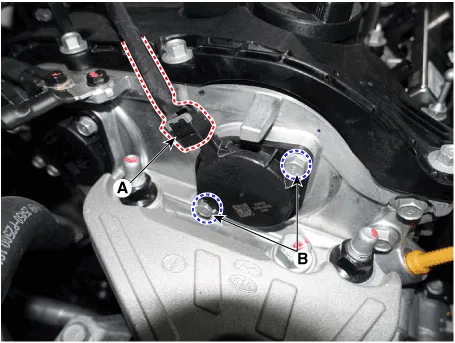
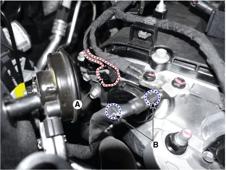
| 2. |
Disconnect the CVVT oil control valve connector (A).
|
| 3. |
Remove the installation bolt (B), and then remove the valve from the
engine.
[Bank 1 / Intake]
[Bank 1 / Exhaust]
|
| Installation |
|

|
| 1. |
Installation is reverse of removal.
|
Circuit Diagram Harness Connector
Description Variable Intake manifold Solenoid (VIS) valve is installed on the intake manifold. The VIS valve controls the vacuum modulator which activates a valve in the intake manifold.
Other information:
Hyundai Santa Fe (TM) 2019-2023 Service and Repair Manual: Specifications
Specification Air Conditioner Item Specification Compressor Type 7HVe17 Oil type & Capacity Single (Front only) FD46XG(IDMITSU) 100± 10cc (3.
Hyundai Santa Fe (TM) 2019-2023 Service and Repair Manual: Compressor. Repair procedures
Removal 1. If a compressor is available, the air conditioner is operated for a few minutes in the engine idle state and then the engine is stopped. 2. Disconnect the negative (-) battery terminal.
Categories
- Manuals Home
- Hyundai Santa Fe Owners Manual
- Hyundai Santa Fe Service Manual
- Engine Mechanical System
- 4 Wheel Drive (4WD) System
- Rear seats
- New on site
- Most important about car

Copyright © 2026 www.hsafe4.com - 0.0185