Hyundai Santa Fe (TM): Hydraulic System / Underdrive Brake Control Solenoid Valve (UD/B_VFS). Specifications
Hyundai Santa Fe (TM) 2019-2023 Service and Repair Manual / Automatic Transaxle System (SBC) / Hydraulic System / Underdrive Brake Control Solenoid Valve (UD/B_VFS). Specifications
| Specifications |
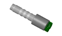
â–· Control type : Normally high type
|
Shape |
Items |
Specifications |
|
|
Control current [mA] |
0 - 1100 |
|
Supply pressure [kpa (kgf/cm², psi)] |
1569.06 (16, 227.57) |
|
|
Control pressure [kpa (kgf/cm², psi)] |
0 - 1569.06 (0 - 16, 0 - 227.57) |
|
| Internal
resistance(Ω) |
5.0 - 5.6 |
Component Location (1)_Valve Body Cover 1. Valve Body Cover 2. Valve Body Cover Gasket 3. Solenoid Valve Connector Component Location (2)_Solenoid Valve 1.
Inspection • Refer to the DTC manual for the check procedure.
Other information:
Hyundai Santa Fe (TM) 2019-2023 Service and Repair Manual: Description and operation
Hyundai Santa Fe (TM) 2019-2023 Service and Repair Manual: Rear Corner Radar System
Description and operation Description Rear Corner Radar is a system that measures the relative speed and distance from the following vehicles by using two electromagnetic wave radar sensors attached to the rear bumper, and detects any vehicle within the blind spot zone and gives off alarm.
Categories
- Manuals Home
- Hyundai Santa Fe Owners Manual
- Hyundai Santa Fe Service Manual
- Rear Disc Brake. Repair procedures
- Power Tailgate Module
- Rear seats
- New on site
- Most important about car

Copyright © 2026 www.hsafe4.com - 0.0236