Hyundai Santa Fe (TM): Automatic Transaxle Control System / Position Switch. Repair procedures
| Inspection |
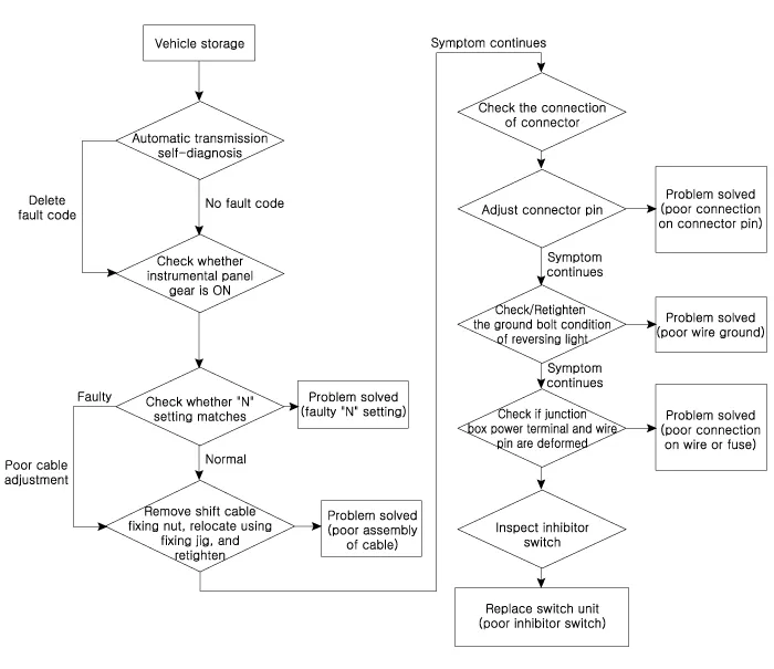
| 1. |
Inspect DTC code.
|
| 2. |
Inspect whether N setting matches.
|
| 3. |
Inspect shift cable separation.
|
| 4. |
Inspect whether connector is connected.
|
| 5. |
Inspect ground condition on reversing light circuit.
|
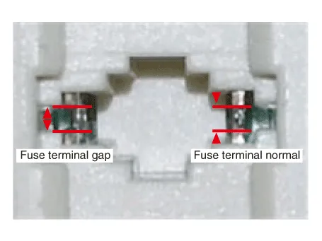
| 6. |
Inspect wiring connection on junction box power terminal and fuse lamp.
|

| 7. |
Inspect inhibitor switch signal.
|
| Removal |
| 1. |
Make sure vehicle does not roll before setting shift lever to "N" position.
|
| 2. |
Turn ignition switch OFF and disconnect the negative (-) battery cable.
|
| 3. |
Remove the air duct and air cleaner assembly.
(Refer to Engine Mechanical System - "Air Cleaner")
|
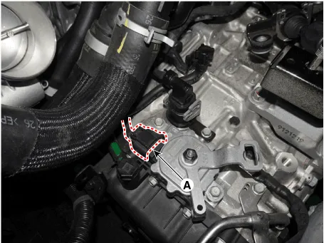
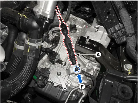
| 4. |
Loosen the nut and then removing the shift cable (A) from position switch.
|

| 5. |
Disconnect the position switch connector (A).
|
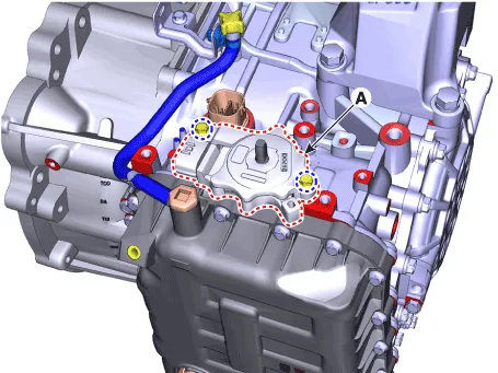
| 6. |
Loosen the nut and then removing the manual lever (A).
|

| 7. |
Loosen the bolts and then removing the position switch (A).
|
| Installation |
| 1. |
Check that the shift lever is placed in the "N" position.
|
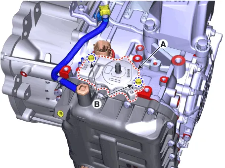
| 2. |
Lightly tighten the bolts (B) after installing the position switch (A).
|
| 3. |
Lightly tighten the nut (B) after installing the manual control lever
(A).
|
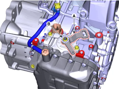
| 4. |
Align the hole in the manual control lever with the "N" position hole
of the inhibitor switch and then insert the position switch guide pin
(SST No. : 09480 - A3800) (A).
|
| 5. |
Tighten the nut (A) and bolts (B) with the specified torque.
|

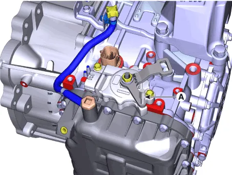
| 6. |
Connect the position switch connector (A).
|
| 7. |
Push nut lightly to "F" direction shown to eliminate free play of shift
cable.
|
| 8. |
Tighten the nut and then install the shift cable (A).
|
| 9. |
Remove the position switch guide pin (SST No. : 09480 - A3800) (A) from
the hole.
|

| 10. |
Install the air cleaner and air duct.
(Refer to Engine Mechanical System - "Air Cleaner")
|
| 11. |
Connect the battery negative (-) cable.
|
| 12. |
Check that operating surely at each range of the inhibitor switch corresponding
to each position of shift lever.
|
Specifications â–· Type : Combination of output signals from 4 terminals â–· Specifications Items Specifications Power supply (V) 12 Output type Combination of output signals
Removal 1. Turn ignition switch OFF and disconnect the negative (-) battery cable. 2. Remove the shift knob & boots.
Other information:
Hyundai Santa Fe (TM) 2019-2023 Service and Repair Manual: IMS (Integrated Memory)
Description and operation Description The optimal seat position set by the driver is memorized into the power seat unit by using IMS switch. In case of the position change, the seat can restore its preset position by IMS switch.
Hyundai Santa Fe (TM) 2019-2023 Service and Repair Manual: A/C Pressure Transducer. Description and operation
Description The A/C Pressure Transducer (APT) converts the pressure value of high pressure line into voltage value after measuring it. By converted voltage value, engine ECU controls the cooling fan by operating it high speed or low speed.
Categories
- Manuals Home
- Hyundai Santa Fe Owners Manual
- Hyundai Santa Fe Service Manual
- Emission Control System
- Rear seats
- Automatic Transaxle Control System
- New on site
- Most important about car
