Hyundai Santa Fe (TM): Automatic Transaxle Control System / Output Speed Sensor. Repair procedures
| Inspection |
|

| Removal |
|

| 1. |
Turn ignition switch OFF and disconnect the negative (-) battery cable.
|
| 2. |
Remove the air cleaner assembly and air duct.
(Refer to Engine Mechanical System - "Air Cleaner")
|
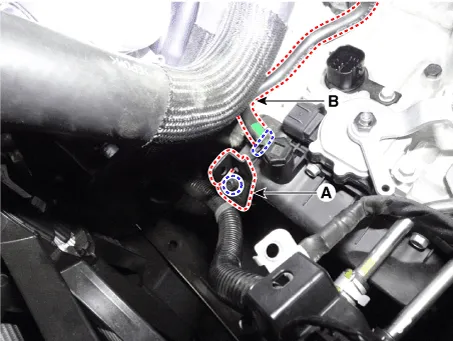
| 3. |
Separate the air bleed hose (B) and then wiring bracket (A).
|
| 4. |
Remove the under cover.
(Refer to Engine Mechanical System - "Engine Room Under Cover")
|
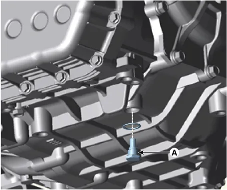
| 5. |
Remove the drain plug (A) and reinstall the drain plug after draining
ATF totally.
|
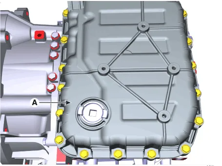
| 6. |
Loosen the mounting bolts (A) of the valve body cover.
|
| 7. |
Loosen the bolts and then removing the main harness (A).
|
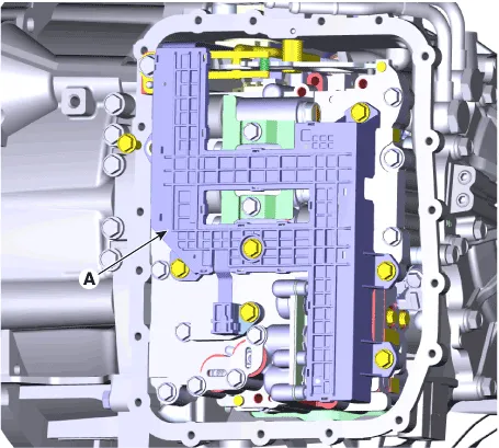
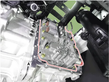
| 8. |
Loosen the mounting bolts and then removing the valve body assembly
(A).
|
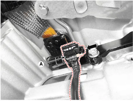
| 9. |
Disconnect the input & output speed sensor connector (A).
|
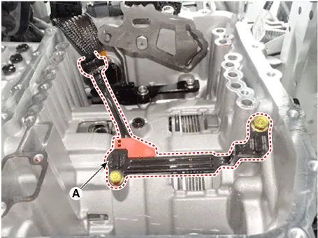
| 10. |
Loosen the bolts and then removing the input / output speed sensor (A).
|
| Installation |
| 1. |
To install, reverse the removal procedure.
|
| 2. |
Check fluid level after filling the automatic transaxle with fluid.
(Refer to Automatic Transaxle Syatem-"Automatic Transaxle Fluid(ATF)")
|
Specifications ▷ Type : Hall effect sensor ▷ Specifications Items Specifications Operation condition [°C(°F)] (-40 to 150) -40 to 302 Output voltage(V) High 1.
Description • The position switch mounted on the upper of transaxle and connected with shifter lever. • The position switch has four points of contact and it makes the signals(S1, S2, S3, S4).
Other information:
Hyundai Santa Fe (TM) 2019-2023 Service and Repair Manual: Windshield Wiper/Washer
Components and components location Component Location 1. Windshield wiper arm & blade 2. Wiper & washer switch 3. Windshield washer hose 4. Windshield wiper motor & linkage 5. Washer motor 6.
Hyundai Santa Fe (TM) 2019-2023 Service and Repair Manual: Auto Head Lamp Leveling Device
Components and components location Component Location 1. Head lamp leveling actuator Head Lamp Leveling Switch. Schematic diagrams Circuit diagram Head Lamp Leveling Switch. Repair procedures Inspection 1.
Categories
- Manuals Home
- Hyundai Santa Fe Owners Manual
- Hyundai Santa Fe Service Manual
- Instrument cluster
- Front Radar Unit. Repair procedures
- Tire Pressure Monitoring System (TPMS)
- New on site
- Most important about car
