
Hyundai Santa Fe (TM): Automatic Transaxle Control System / Input Speed Sensor. Repair procedures
| Inspection |
|

| Removal |
|

| 1. |
Turn ignition switch OFF and disconnect the negative (-) battery cable.
|
| 2. |
Remove the air duct and the air cleaner assembly.
(Refer to Engine Mechanical System - "Air Cleaner")
|
| 3. |
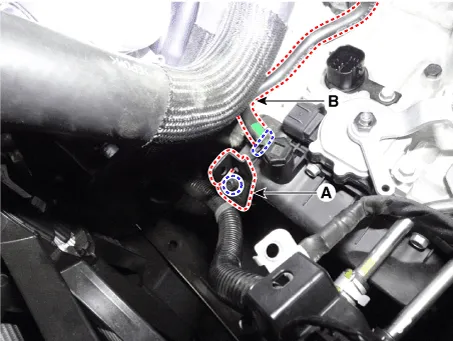
Separate the air bleed hose (B) and then wiring bracket (A).
|
| 4. |
Remove the under cover.
(Refer to Engine Mechanical System - "Engine Room Under Cover")
|
| 5. |
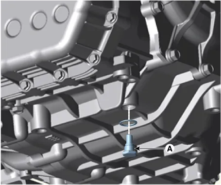
Remove the drain plug (A) and reinstall the drain plug after draining
ATF totally.
|
| 6. |
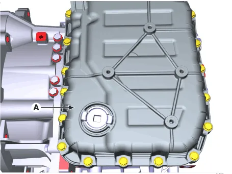
Loosen the mounting bolts (A) of the valve body cover.
|
| 7. |
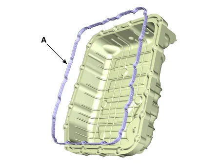
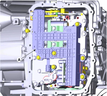
Loosen the bolts and then removing the main harness (A).
|
| 8. |
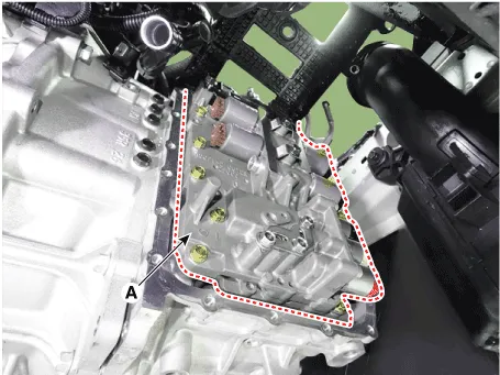
Loosen the mounting bolts and then removing the valve body assembly
(A).
|
| 9. |
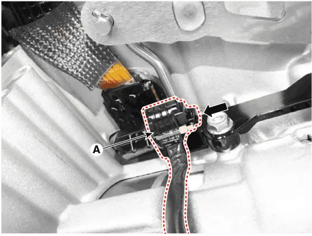
Disconnect the input & output speed sensor connector (A).
|
| 10. |
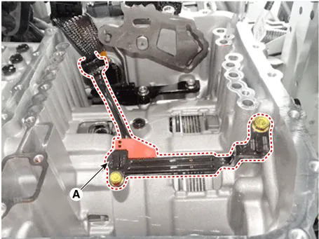
Loosen the bolts and then removing the input / output speed sensor (A).
|
| Installation |
| 1. |
To install, reverse the removal procedure.
|
| 2. |
Check fluid level after filling the automatic transaxle with fluid.
(Refer to Automatic Transaxle Syatem-"Automatic Transaxle Fluid(ATF)")
|
Specifications ▷ Type : Hall effect sensor ▷ Specifications Items Specifications Operation condition [°C(°F)] (-40 to 150) -40 to 302 Sensor length (mm) 35.
Description The output speed sensor is a vital unit that measures the rate of rotation of the transaxle's turbine shaft and output shaft, and delivers the readings to the TCM.
Other information:
Hyundai Santa Fe (TM) 2019-2023 Service and Repair Manual: Smart Key Diagnostic. Repair procedures
Inspection Self Diagnosis With Scan Tool It will be able to diagnose defects of SMART KEY system with diagnostic tool quickly. diagnostic tool can operates actuator forcefully, input/output value monitoring and self diagnosis.
Hyundai Santa Fe (TM) 2019-2023 Service and Repair Manual: Electro Chromic Inside Rear View Mirror
Description and operation Description The ECM (Electro Chromatic inside rear view Mirror) is intended dim the reflecting light in the rear view mirror. The forward facing sensor detects brightness of the surroundings, while the rearward looking sensor is for the light from the rear.
Categories
- Manuals Home
- Hyundai Santa Fe Owners Manual
- Hyundai Santa Fe Service Manual
- Vehicle Information, Consumer Information and Reporting Safety Defects
- 4 Wheel Drive (4WD) System
- Identification Numbers
- New on site
- Most important about car
