Hyundai Santa Fe (TM): Engine Control System / Injector. Repair procedures
| Inspection |
| 1. |
Turn the ignition switch OFF.
|
| 2. |
Disconnect the injector connector.
|
| 3. |
Measure resistance between the injector terminals 1 and 2.
|
| 4. |
Check that the resistance is within the specification.
|
| Removal |
| 1. |
Release the residual pressure in fuel line.
Release the residual pressure in fuel line.
|
| 2. |
Turn the ignition switch OFF and disconnect the battery (-) terminal.
|
| 3. |
Disconnect the fuel delivery line quick-connector (A).
|


| 4. |
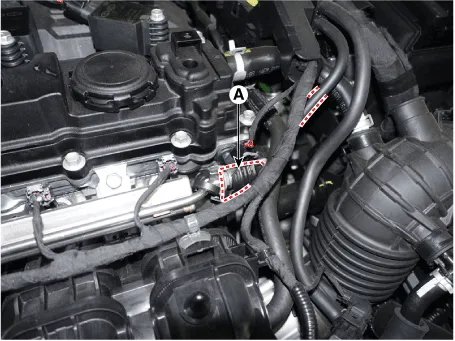
Disconnect the injector connector (A).
|

| 5. |
Remove the delivery pipe & injector assembly after loosening the bolt
(A).
|

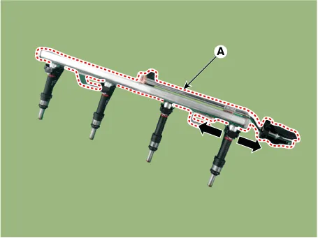
| 6. |
Remove the injector from the delivery pipe (A) after releasing the fixing
clip both side as shown below.
|
| Installation |
|
|
|
| 1. |
Installation is reverse of removal.
|
Circuit Diagram Harness Connector
Description Purge Control Solenoid Valve (PCSV) is installed on the surge tank and controls the passage between the canister and the intake manifold.
Other information:
Hyundai Santa Fe (TM) 2019-2023 Service and Repair Manual: Electro Chromic Inside Rear View Mirror
Description and operation Description The ECM (Electro Chromatic inside rear view Mirror) is intended dim the reflecting light in the rear view mirror. The forward facing sensor detects brightness of the surroundings, while the rearward looking sensor is for the light from the rear.
Hyundai Santa Fe (TM) 2019-2023 Service and Repair Manual: Rear Heater
Rear Heater Unit. Components and components location Component Location 1. Rear Heater & A/C Unit Components 1. Rear heater & blower unit assembly 2. Blower motor assembly 3.
Categories
- Manuals Home
- Hyundai Santa Fe Owners Manual
- Hyundai Santa Fe Service Manual
- Instrument cluster
- Blower
- 4 Wheel Drive (4WD) System
- New on site
- Most important about car
