Hyundai Santa Fe (TM): Smart Key System / Smart Key Unit. Repair procedures
| Removal |
| 1. |
Disconnect the negative (-) battery terminal.
|
| 2. |
Remove the glove box.
(Refer ti Body - "Glove Box")
|
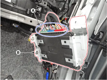
| 3. |
Remove the smart key unit (B) after loosening the mounting bolts(2EA)
and disconnecting the connector (A).
|
| Inspection |
| Installation |
| 1. |
Install the smart key unit.
|
| 2. |
Install the smart key unit mounting bolts and connect the connector.
|
| 3. |
Install the driver side crash pad lower panel.
|
| 4. |
Install the negative (-) battery terminal and check the smart key system.
|
Circuit Diagram
Inspection Self Diagnosis With Scan Tool It will be able to diagnose defects of SMART KEY system with diagnostic tool quickly. diagnostic tool can operates actuator forcefully, input/output value monitoring and self diagnosis.
Other information:
Hyundai Santa Fe (TM) 2019-2023 Service and Repair Manual: Windshield Wiper/Washer
Components and components location Component Location 1. Windshield wiper arm & blade 2. Wiper & washer switch 3. Windshield washer hose 4. Windshield wiper motor & linkage 5. Washer motor 6.
Hyundai Santa Fe (TM) 2019-2023 Service and Repair Manual: Controller
Heater & A/C Control Unit (Manual). Components and components location Component Connector Pin Function Pin No Connector A Connector B 1 Battery Low 2 ISG B+ Common 3
Categories
- Manuals Home
- Hyundai Santa Fe Owners Manual
- Hyundai Santa Fe Service Manual
- Engine Electrical System
- Brake System
- Troubleshooting
- New on site
- Most important about car
