Hyundai Santa Fe (TM): Smart Key System / Smart key antenna. Repair procedures
| Removal |
Take care not to scratch the crash pad and related parts.
|

| 1. |
Disconnect the negative (-) battery terminal.
|
| 2. |
Remove the crash pad center panel.
(Refer to Body - "Crash Pad Center Panel")
|
| 3. |
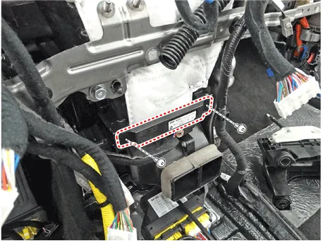
Remove the interior 1 antenna after loosening the mounting nuts (2EA)
and disconnecting the connector.
|
| 1. |
Disconnect the negative (-) battery terminal.
|
| 2. |
Remove the console rear complete assembly.
(Refer to Body - "Floor Console Assembly")
|
| 3. |
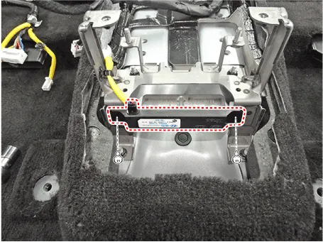
Remove the interior 2 antenna after loosening the mounting nuts (2EA)
and disconnecting the connector.
|
| 1. |
Disconnect the negative (-) battery terminal.
|
| 2. |
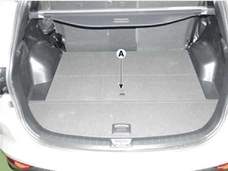
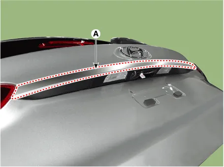
Remove the luggage covering mat (A).
|
| 3. |
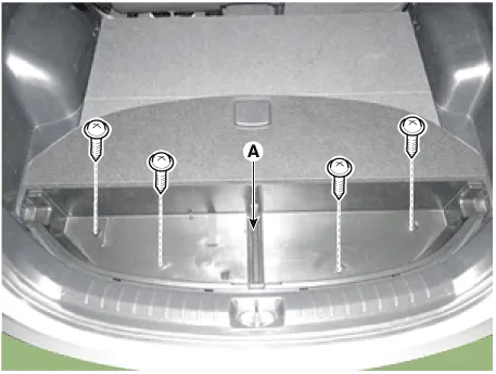
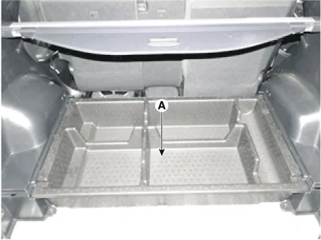
Remove the luggage floor box (A) after loosening the screws (4EA).
|
| 4. |
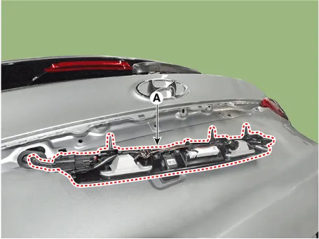
Remove the luggae tray box (A).
|
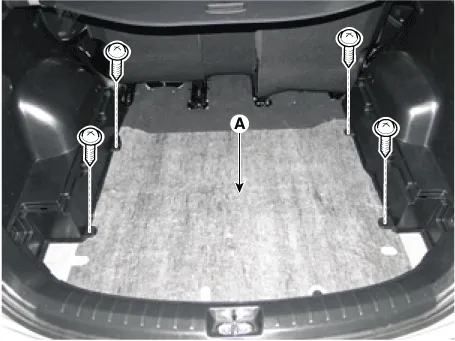
| 5. |
Remove the floor mat (A) after loosening the screws (4EA).
|
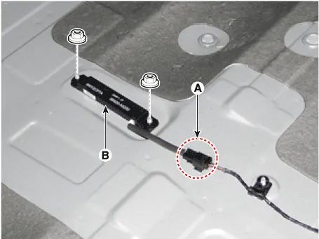
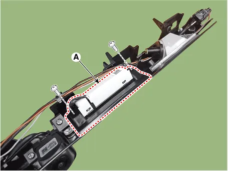
| 6. |
Remove the interior 3 antenna (B) after loosening the mounting screws(2EA)
and disconnecting the connector (A).
|
| 1. |
Disconnect the negative (-) battery terminal.
|
| 2. |
Lift the vehicle.
|
| 3. |
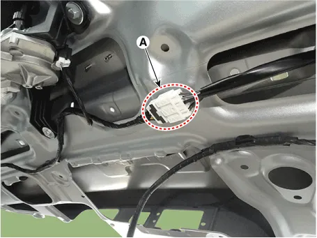
Disconnect the antenna connector from the rear bumper.
|
| 4. |
After loosening the nuts (2EA), remove the exterior bumper antenna.
|
| 1. |
Disconnect the negative (-) battery terminal.
|
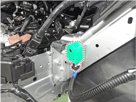
| 2. |
Remove the front left wheel guide.
|
| 3. |
Disconnect the connectors, then remove the buzzer (A).
|
| 1. |
Disconnect the negative (-) battery terminal.
|
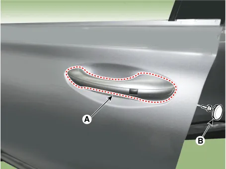
| 2. |
Remove the door outside handle cover (A) after seperating the plug hole
(B) from the door by loosening the mounting bolt.
|
| 3. |
Disconnect the door outside handle connector.
|
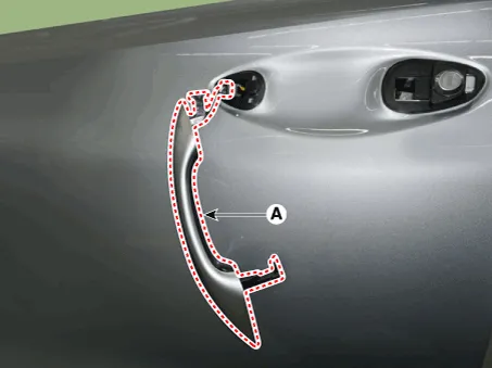
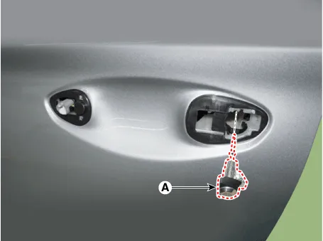
| 4. |
Remove the front door lock assembly (A).
|
| 1. |
Disconnect the negative (-) battery terminal.
|
| 2. |
Remove the tailgate trim.
(Refer to Body - "Tailgate Trim")
|
| 3. |
Remove the tailgate ganish (A) after loosening the mounting nuts.
|
| 4. |
Disconnect the tailgate switch connector (A).
|
| 5. |
Remove the tailgate switch assembly (A).
|
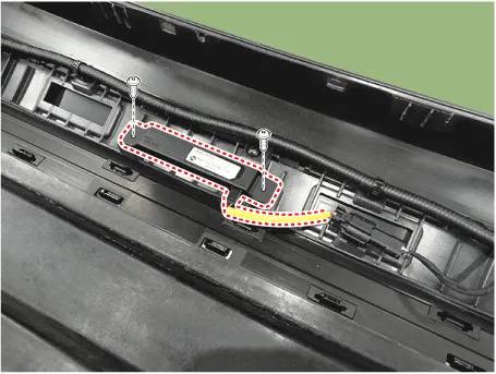
| 6. |
Remove the tailgate switch (A) after loosening the screw.
|
| Installation |
| 1. |
Install the interior 1 antenna.
|
| 2. |
Install the crash pad center panel.
|
| 3. |
Install the negative (-) battery terminal and check the smart key system.
|
| 1. |
Install the interior 2 antenna.
|
| 2. |
Install the console rear complete assembly.
|
| 3. |
Install the negative (-) battery terminal and check the smart key system.
|
| 1. |
Install the interior 3 antenna.
|
| 2. |
Install the floor mat, the luggage tray box, the luggage floor box and
luggage covering mat.
|
| 3. |
Install the negative (-) battery terminal and check the smart key system.
|
| 1. |
Install the exterior bumper antenna.
|
| 2. |
Install the rear bumper cover.
|
| 3. |
Install the negative (-) battery terminal and check the smart key system.
|
| 1. |
Install the buzzer.
|
| 2. |
Install the front left wheel guide.
|
| 3. |
Install the negative (-) battery terminal and check the smart key system.
|
| 1. |
Install the outside handle.
|
| 2. |
Install the door trim.
|
| 3. |
Install the negative (-) battery terminal and check the smart key system.
|
| 1. |
Install the tailgate switch.
|
| 2. |
Install the tailgate garnish.
|
| 3. |
Install the tailgate trim.
|
| 4. |
Install the negative (-) battery terminal and check the smart key system.
|
Inspection Self Diagnosis With Scan Tool It will be able to diagnose defects of SMART KEY system with diagnostic tool quickly. diagnostic tool can operates actuator forcefully, input/output value monitoring and self diagnosis.
Description and operation Description Burglar Alarm State [B/A State] B/A State Description DISARM 1) In "DISARM" state, no vehicle start inhibition.
Other information:
Hyundai Santa Fe (TM) 2019-2023 Service and Repair Manual: Immobilizer System
Description and operation Description The immobilizer system will disable the vehicle unless the proper ignition key is used, in addition to the currently available anti-theft systems such as car alarms, the immobilizer system aims to drastically reduce the rate of auto theft.
Hyundai Santa Fe (TM) 2019-2023 Service and Repair Manual: Front View Camera System
Description and operation Description and Operation Blcok Diagram • This system monitors the driving situations through the radar and the camera.
Categories
- Manuals Home
- Hyundai Santa Fe Owners Manual
- Hyundai Santa Fe Service Manual
- Automatic Transaxle Control System
- Battery. Specifications
- Vehicle Information, Consumer Information and Reporting Safety Defects
- New on site
- Most important about car
