Hyundai Santa Fe (TM): ETC (Electronic Throttle Control) System / Repair procedures
Throttle Position Sensor (TPS)
|
1. |
Connect the diagnostic tool on the Data Link Connector (DLC).
|
|
2. |
Start the engine and measure the output voltage of TPS 1 and 2 at C.T.
and W.O.T.
Throttle Angle
|
Output Voltage (V)
|
TPS 1
|
TPS 2
|
C.T
|
0.3 - 0.9
|
4.2 - 5.0
|
W.O.T
|
1.5 - 3.0
|
3.3 - 3.8
|
|
|
3. |
Turn the ignition switch OFF and disconnect the scantool from the DLC.
|
|
4. |
Disconnect the ETC module connector and measure the resistance between
the ETC module terminals 1 and 2.
|
Specification : Refer to "Specification"
|
|
ETC Motor
|
1. |
Turn the ignition switch OFF.
|
|
2. |
Disconnect the ETC module connector.
|
|
3. |
Measure resistance between the ETC module terminals 3 and 6.
|
|
4. |
Check that the resistance is within the specification.
|
Specification : Refer to "Specification"
|
|
|
1. |
Turn the ignition switch OFF and disconnect the battery negative (-)
cable.
|
|
2. |
Remove the resonator and the air intake hose.
(Refer to Engine Mechanical System - "Intake Manifold")
|
|
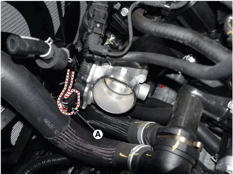
3. |
Disconnect the ETC module connector (A).
|
|
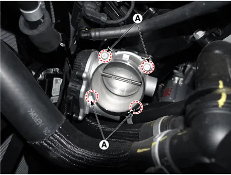
4. |
Remove the installation bolts (A), and then remove the ETC module from
the engine.
|
Tightening Torque :
7.8 - 11.8 N.m (0.8 - 1.2 kgf.m, 5.8 - 8.7 lb-ft)
|
|
| •
|
Install the component with the specified torques.
|
| •
|
Note that internal damage may occur when the component is dropped.
In this case, use it after inspecting.
|
|
|
1. |
Installation is reverse of removal.
|
Schematic Diagram
Circuit Diagram
Harness Connector
Description
Manifold Absolute Pressure Sensor (MAPS) is a speed-density type sensor and
is installed on the surge tank. It senses absolute pressure of the surge tank
and transfers the analog signal proportional to the pressure to the ECM.
Other information:
Inspection
1.
Turn the ignition switch OFF.
2.
Disconnect the temperature control actuator connector.
3.
Verify that the temperature control actuator operates to the cool position
when connecting 12V to terminal 3 and grounding terminal 7.
Replacement
1.
Disconnect the negative (-) battery terminal.
2.
Remove the luggage side trim [RH].
(Refer to Body - "Luggage Side Trim")
3.
Separate the blower motor connector (A) and loosen the mounting screws
and remove the

