Hyundai Santa Fe (TM): Engine Control System / ETC (Electronic Throttle Control) System
Description and operation
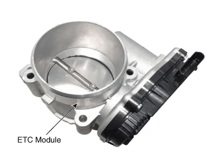
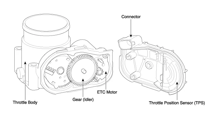
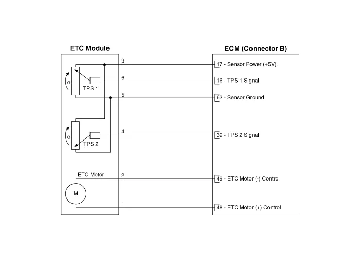
The Electronic Throttle Control (ETC) System consists of a throttle body with
an integrated control motor and throttle position sensor (TPS). Instead of the
traditional throttle cable, an Accelerator Position Sensor (APS) is used to
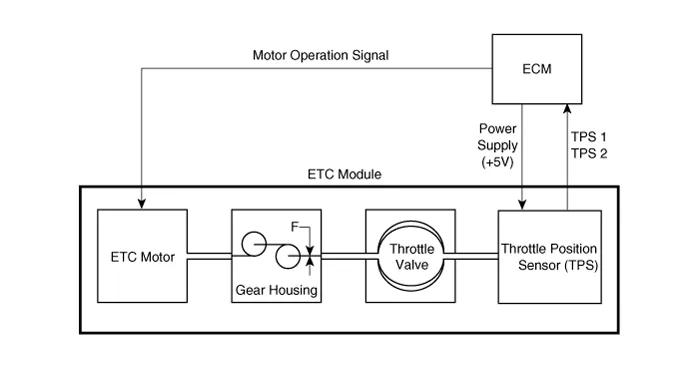
receive driver input. The ECM uses the APS signal to calculate the target throttle
angle; the position of the throttle is then adjusted via ECM control of the
ETC motor. The TPS signal is used to provide feedback regarding throttle position
to the ECM. Using ETC, precise control over throttle position is possible; the
need for external cruise control modules/cables is eliminated.
Troubleshooting
Item
|
Fail-Safe
|
ETC Motor
|
Throttle valve stuck at 5°
|
TPS
|
TPS 1 fault
|
Replace it with TPS2
|
TPS 2 fault
|
Replace it with TPS1
|
TPS 1, 2 fault
|
Throttle valve stuck at 5°
|
APS
|
TPS 1 fault
|
Replace it with TPS2
|
TPS 2 fault
|
Replace it with TPS1
|
TPS 1, 2 fault
|
Throttle valve stuck at 5°
|
| •
|
When throttle value is stuck at 5°, engine speed is limited
at below 1,500rpm and vehicle speed at maximum 40 - 50 km/h
(25 - 31 mph).
|
|
Specifications
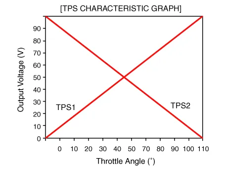
[Throttle Position Sensor (TPS)]
Throttle Angle (°)
|
Output Voltage (V)
|
TPS1
|
TPS2
|
0
|
0.0
|
5.0
|
10
|
0.48
|
4.52
|
20
|
0.95
|
4.05
|
30
|
1.43
|
3.57
|
40
|
1.90
|
3.10
|
50
|
2.38
|
2.62
|
60
|
2.86
|
2.14
|
70
|
3.33
|
1.67
|
80
|
3.81
|
1.19
|
90
|
4.29
|
0.71
|
100
|
4.76
|
0.24
|
105
|
5.0
|
0
|
C.T (6 - 15°)
|
0.29 - 0.71
|
4.29 - 4.71
|
W.O.T (93 - 102°)
|
4.43 - 4.86
|
0.14 - 0.57
|
Item
|
Sensor Resistance (kΩ)
|
TPS1
|
0.875 - 1.625 [20°C (68°F)]
|
TPS2
|
0.875 - 1.625 [20°C (68°F)]
|
[ETC Motor]
Item
|
Specification
|
Coil Resistance (Ω)
|
1.2 - 1.8 [20°C (68°F)]
|
Schematic diagrams
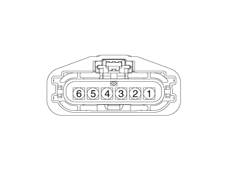
Harness Connector
Repair procedures
Throttle Position Sensor (TPS)
|
1. |
Connect the diagnostic tool on the Data Link Connector (DLC).
|
|
2. |
Start the engine and measure the output voltage of TPS 1 and 2 at C.T.
and W.O.T.
Throttle Angle
|
Output Voltage (V)
|
TPS 1
|
TPS 2
|
C.T
|
0.3 - 0.9
|
4.2 - 5.0
|
W.O.T
|
1.5 - 3.0
|
3.3 - 3.8
|
|
|
3. |
Turn the ignition switch OFF and disconnect the scantool from the DLC.
|
|
4. |
Disconnect the ETC module connector and measure the resistance between
the ETC module terminals 1 and 2.
|
Specification : Refer to "Specification"
|
|
ETC Motor
|
1. |
Turn the ignition switch OFF.
|
|
2. |
Disconnect the ETC module connector.
|
|
3. |
Measure resistance between the ETC module terminals 3 and 6.
|
|
4. |
Check that the resistance is within the specification.
|
Specification : Refer to "Specification"
|
|
|
1. |
Turn the ignition switch OFF and disconnect the battery negative (-)
cable.
|
|
2. |
Remove the resonator and the air intake hose.
(Refer to Engine Mechanical System - "Intake Manifold")
|
|
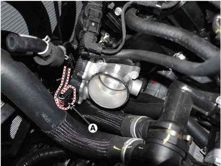
3. |
Disconnect the ETC module connector (A).
|
|
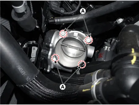
4. |
Remove the installation bolts (A), and then remove the ETC module from
the engine.
|
Tightening Torque :
7.8 - 11.8 N.m (0.8 - 1.2 kgf.m, 5.8 - 8.7 lb-ft)
|
|
| •
|
Install the component with the specified torques.
|
| •
|
Note that internal damage may occur when the component is dropped.
In this case, use it after inspecting.
|
|
|
1. |
Installation is reverse of removal.
|
Removal
•
If you replace the PCM, you must perform oil pressure characteristics
back up & input (TCU Replacement).
Description
Manifold Absolute Pressure Sensor (MAPS) is a speed-density type sensor and
is installed on the surge tank. It senses absolute pressure of the surge tank
and transfers the analog signal proportional to the pressure to the ECM.
Other information:
Description
The SMART KEY system is a system that allows the user to access and operate
a vehicle in a very convenient way. To access the vehicle, no traditional key
or remote control unit is needed.
The user carries a SMART KEY FOB which does not require any conscious actions
by the user (e.
Description and operation
Description and Operation
Blcok Diagram
•
This system monitors the driving situations through the radar
and the camera.


