Hyundai Santa Fe (TM): ESP(Electronic Stability Program) System / Rear Wheel Speed Sensor. Repair procedures
| Removal |
|

| 1. |
Loosen the wheel nuts slightly.
Raise the vehicle, and make sure it is securely supported.
|
| 2. |
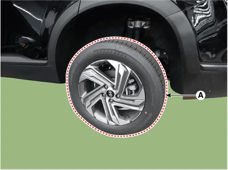
Remove the rear wheel and tire (A) from the rear hub.
|

| 3. |
Remove the rear brake caliper.
(Refer to Brake System - "Rear Disc Brake")
|
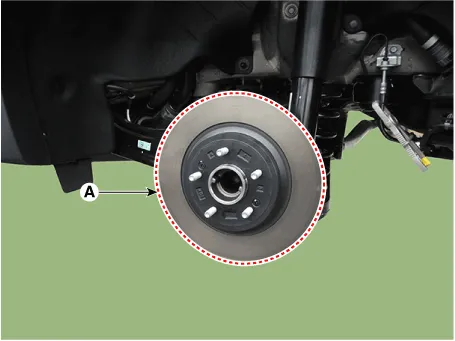
| 4. |
Loosen the screw and the remove the rear break disc.
|
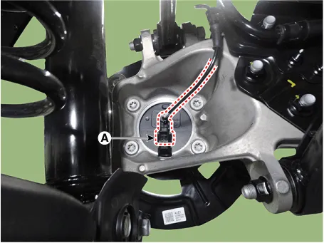
| 5. |
Disconnect the rear wheel speed sensor connector (A).
|
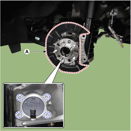
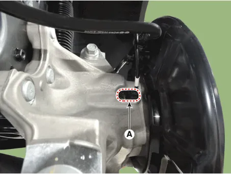
| 6. |
Loosen the bearing mounting bolts and then remove the hub bearing assembly
& dust cover (A).
|
| 1. |
Loosen the wheel nuts slightly.
Raise the vehicle, and make sure it is securely supported.
|
| 2. |
Remove the rear wheel and tire (A) from the rear hub.
|
| 3. |
Remove the rear wheel guard.
(Refer to Body - "Rear Wheel Guard")
|
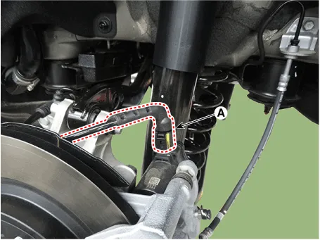
| 4. |
Disconnect the rear wheel speed sensor connector (A).
|
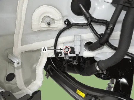
| 5. |
Remove the rear wheel speed sensor cable braket bolt (A).
|
| 6. |
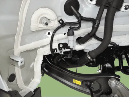
Disconnect the EPB actuator connetor (A).
|
| 7. |
Disconnect the rear wheel speed sensor connector (A).
|
| Replacement |
| 1. |
Remove the rear wheel hub bearing assembly.
(Refer to Driveshaft and Axle - "Rear Hub - Carrier")
|
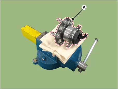
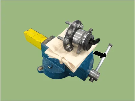
| 2. |
Fix the rear hub bearing assembly (A) on the vise.
|
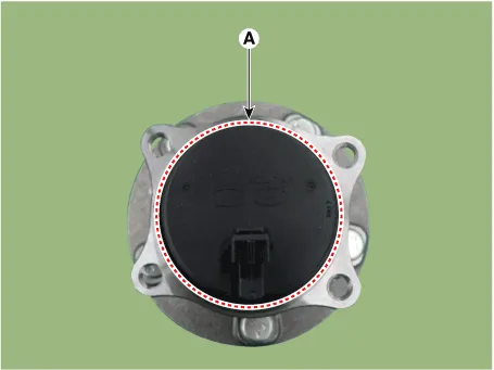
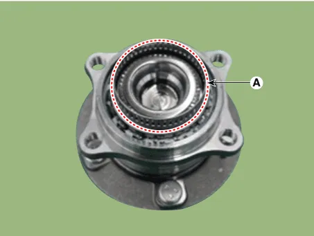
| 3. |
Check the direction of the sensor cap (A).
|
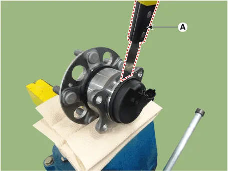
| 4. |
Remove the sensor cap by hammering on a gap between sensor cap and hub
bearing assembly using a scraper (A).
|
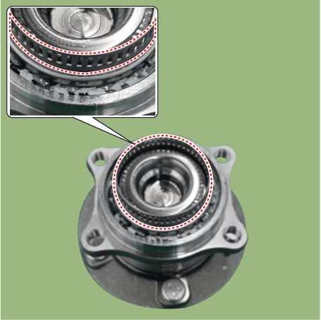
| 5. |
Check if distorted or damaged the tone wheel or encoder (A).
|
| 6. |
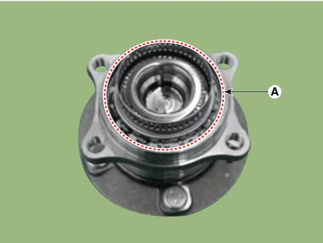
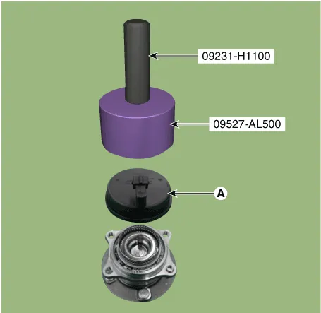
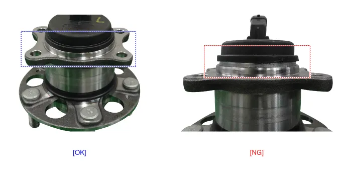
Position the sensor cap to the same direction of sensor cap connector
(A) as you checked before removing.
|
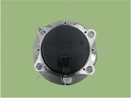
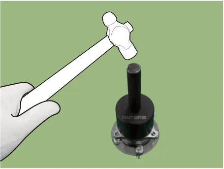
| 7. |
Install the sensor cap (A) with the special service tool (09527-AL500).
|
| 8. |
Install the rear wheel hub bearing assembly.
(Refer to Driveshaft and Axle - "Rear Hub - Carrier")
|
| Inspection |
| 1. |
Measure the output voltage between the terminal of the wheel speed sensor
and the body ground.
|
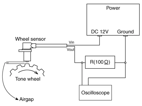
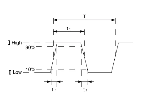
| 2. |
Compare the change of the output voltage of the wheel speed sensor to
the normal change of the output voltage as shown below.
|
| Installation |
| 1. |
Install in the reverse order of removal.
|
Components [2WD] 1. Rear wheel speed sensor [4WD] 1. Rear wheel speed sensor 2.
Description Introduction of quick brake warning system (ESS) In case of quick brake by driver, the brake lamp or turn signal is blinked to warn against the vehicle at rear.
Other information:
Hyundai Santa Fe (TM) 2019-2023 Service and Repair Manual: IMS (Integrated Memory)
Description and operation Description The optimal seat position set by the driver is memorized into the power seat unit by using IMS switch. In case of the position change, the seat can restore its preset position by IMS switch.
Hyundai Santa Fe (TM) 2019-2023 Service and Repair Manual: Lighting System
Components and components location Component Location 1. Head lamp (Low) 2. Head lamp (High) 3. Daytime running light (DRL)/Positioning lamp 4. Turn signal lamp 5. Head lamp (ADD Low) 6. Side repeater lamp 7.
Categories
- Manuals Home
- Hyundai Santa Fe Owners Manual
- Hyundai Santa Fe Service Manual
- Emission Control System
- Automatic Transaxle Control System
- Hydraulic System
- New on site
- Most important about car
