Hyundai Santa Fe (TM): Power Windows / Power Window Switch. Repair procedures
Hyundai Santa Fe (TM) 2019-2023 Service and Repair Manual / Body Electrical System / Power Windows / Power Window Switch. Repair procedures
| Diagnosis with diagnostic tool |
Diagnosis with diagnostic tool
| 1. |
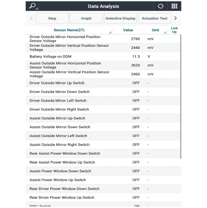
In the body electrical system, failure can be quickly diagnosed by using
the vehicle diagnostic system (diagnostic tool).
The diagnostic system (diagnostic tool) provides the following information.
|
| 2. |
If diagnose the vehicle by diagnostic tool, select "DTC Analysis" and
"Vehicle".
|

| 3. |
Select the 'Data Analysis' and 'Car model'.
|

| 4. |
Select the 'DDM' to search the current state of the input/output data.
|
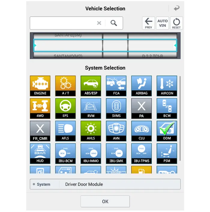
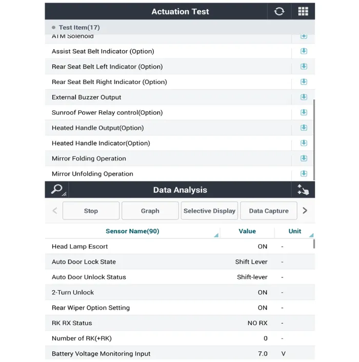
| 5. |
To forcibly actuate the input value of the module to be checked, select
option 'Actuation Test'.
|
| Removal |
Driver Power Window Switch
| 1. |
Disconnect the negative (-) battery terminal.
|
| 2. |
Remove the front door trim.
(Refer to Body - "Front Door Trim")
|
| 3. |
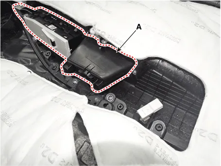
Remove the power window bezzel assembl (A) after loosening the mounting
screws.
|
| 4. |
Remove the power window switch assembly (A) after loosening the mounting
screws.
|
Assist Power Window Switch
| 1. |
Disconnect the negative (-) battery terminal.
|
| 2. |
Remove the front door trim.
(Refer to Body - "Front Door Trim")
|
| 3. |
Remove the power window switch assembly (A) after loosening the mounting
screws.
|
Rear Power Window Swtich
| 1. |
Disconnect the negative (-) battery terminal.
|
| 2. |
Remove the rear door trim.
(Refer to Body - "Rear Door Trim")
|
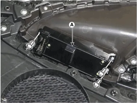
| 3. |
Remove the power window switch assembly (A) after loosening the mounting
screws.
|
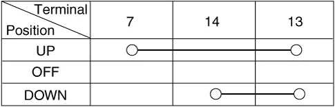
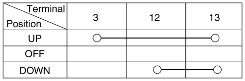
| 4. |
Check for continuity between the terminals in each switch position according
to the table. If the continuity condition is not normal, replace the
switch.
[Manual Window]
[Safety Window]
|
| Installation |
Driver Power Window Switch
| 1. |
Install the power window switch assembly.
|
| 2. |
Install the front door trim after connecting the connector.
|
Assist Power Window Switch
| 1. |
Install the power window switch assembly.
|
| 2. |
Install the front door trim after connecting the connector.
|
Rear Power Window Swtich
| 1. |
Install the power window switch assembly.
|
| 2. |
Install the rear door trim after connecting the connector.
|
Circuit Diagram [Driver Power Window Switch] Driver safety switch Front safety switch ALL safety switch [Assist Power Window Switch] [Rear Power Window Switch]
Other information:
Hyundai Santa Fe (TM) 2019-2023 Service and Repair Manual: Temperature Control Actuator. Repair procedures
Inspection 1. Turn the ignition switch OFF. 2. Disconnect the temperature control actuator connector. 3. Verify that the temperature control actuator operates to the cool position when connecting 12V to terminal 3 and grounding terminal 7.
Hyundai Santa Fe (TM) 2019-2023 Service and Repair Manual: Surround View Monitor (SVM) Unit. Components and components location
Categories
- Manuals Home
- Hyundai Santa Fe Owners Manual
- Hyundai Santa Fe Service Manual
- Driving your vehicle
- Description and operation
- Rear Bumper Assembly. Repair procedures
- New on site
- Most important about car

Copyright © 2025 www.hsafe4.com - 0.0157