Hyundai Santa Fe (TM): Power Door Locks / Power Door Lock Actuators. Repair procedures
| Inspection |
| 1. |
Remove the front door trim.
(Refer to Body - "Front Door Trim")
|
| 2. |
Remove the front door module.
(Refer to Body - "Front Door Module")
|
| 3. |
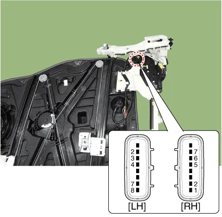
Disconnect the connectors from the actuator.
|

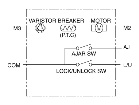
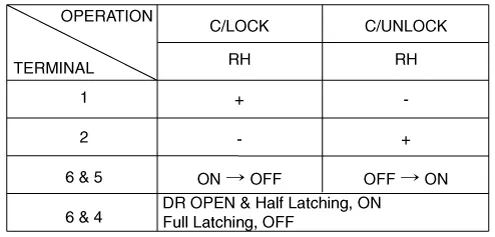
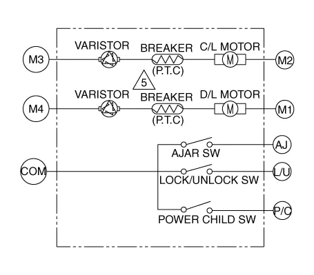
| 4. |
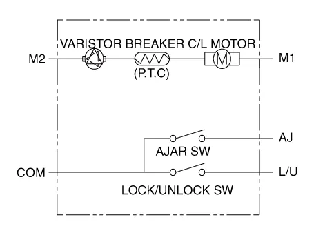
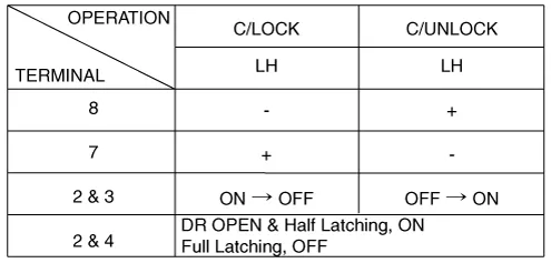
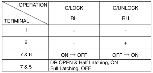
Check actuator operation by connecting power and ground according to
the table.
[Dead Lock]
[Central Lock]
[Central Lock]
[Dead Lock]
Driver
Passenger
|


| 1. |
Remove the rear door trim.
(Refer to Body - "Rear Door Trim")
|
| 2. |
Remove the rear door module.
(Refer to Body - "Rear Door Module")
|
| 3. |
Disconnect the connectors from the actuator.
|
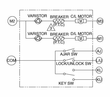
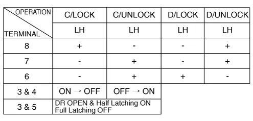
| 4. |
Check actuator operation by connecting power and ground according to
the table.
[Central Lock]
[Dead Lock]
[Child Lock]
|

| 1. |
Remove the tailgate trim.
(Refer to Body - "Tailgate Trim")
|
| 2. |
Disconnect the 4P connector from the actuator.
|
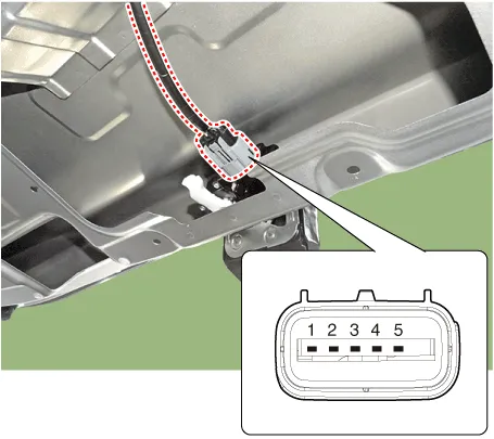
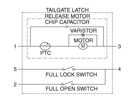
| 3. |
Check actuator operation by connecting power and ground according to
the table.
|

| 1. |
Disconnect the connector and bolts from the hood switch.
|
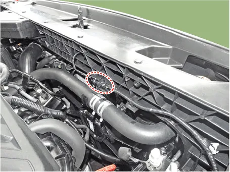
| 2. |
Check for continuity between the terminals and ground according to the
table.
|

Component Location 1. Driver power window main switch 2. IBU (Integrated Body Control Unit) 3. Door lock switch 4.
Diagnosis with Diagnostic Tool 1. In the body electrical system, failure can be quickly diagnosed by using the vehicle diagnostic system.
Other information:
Hyundai Santa Fe (TM) 2019-2023 Service and Repair Manual: Schematic diagrams
System Block Diagram Component Parts And Function Outline Component part Function Vehicle-speed sensor, ESP/ABS Control Module Converts vehicle speed to pulse. ECM Receives signals from sensor and control switches.
Hyundai Santa Fe (TM) 2019-2023 Service and Repair Manual: Remote Smart Parking Assist (RSPA). Repair procedures
Removal ADAS Parking ECU (ADAS_PRK) 1. Disconnect the negative (-) battery terminal. 2. Remove the ADAS Parking ECU (ADAS_PRK). (Refer to Advanced Driver Assistance System (ADAS) - "ADAS Parking ECU (ADAS_PRK)") Parking/View switch
Categories
- Manuals Home
- Hyundai Santa Fe Owners Manual
- Hyundai Santa Fe Service Manual
- Folding the side view mirror
- Convenience features
- Driver assistance system
- New on site
- Most important about car
