Hyundai Santa Fe (TM): Hydraulic System / Overdrive Clutch Control Solenoid Valve (OD/C_VFS). Specifications
| Specifications |
|
Shape |
Items |
Specifications |
|
|
Control current [mA] |
0 - 1100 |
|
Supply pressure [kpa (kgf/cmôý, psi)] |
1569.06 (16, 227.57) |
|
|
Control pressure [kpa (kgf/cmôý, psi)] |
0 - 1569.06 (0 - 16, 0 - 227.57) |
|
| Internal
resistance(ãÎ) |
5.0 - 5.6 |
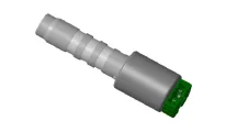
Component Location (1)_Valve Body Cover 1. Valve Body Cover 2. Valve Body Cover Gasket 3. Solenoid Valve Connector Component Location (2)_Solenoid Valve 1.
Inspection ã Refer to the DTC manual for the check procedure.
Other information:
Hyundai Santa Fe (TM) 2019-2023 Service and Repair Manual: Panorama Sunroof
Components and components location Component Location 1. Panorama sunroof 2. Panorama sunroof switch 3. Panorama sunroof motor & controller 4. Roller blind motor & slave controller Schematic diagrams Circuit Diagram Connector Pin Information No
Hyundai Santa Fe (TM) 2019-2023 Service and Repair Manual: Rear Occupant Alert
Description and operation Description The system detects the passenger in the vehicle and prevents the driver from getting off the vehicle with the passenger in the back. - 1st warning: If you open the driver's door after you open and then close the rear passenger and turn the engine off, the system provides warn
Categories
- Manuals Home
- Hyundai Santa Fe Owners Manual
- Hyundai Santa Fe Service Manual
- Front Radar Unit. Repair procedures
- Rear Disc Brake. Repair procedures
- Troubleshooting
- New on site
- Most important about car
