Hyundai Santa Fe (TM): Body Electrical System / Multifunction Switch
Hyundai Santa Fe (TM) 2019-2023 Service and Repair Manual / Body Electrical System / Multifunction Switch
Components and components location
| Component |
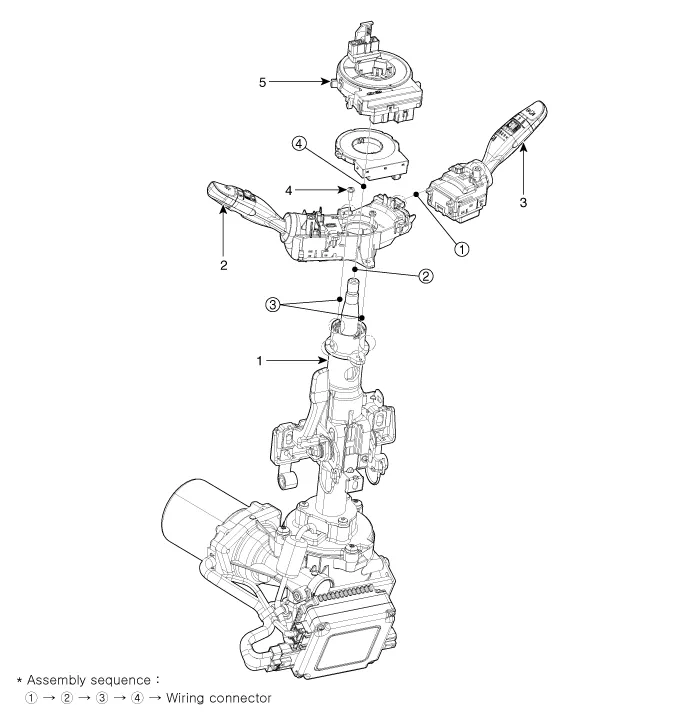
| 1. Steering column 2. Multifunction switch |
3. Screw 4. Clock spring |
Specifications
| Specifications |
|
Items |
Specifications |
|
|
Rated voltage |
DC 12V |
|
|
Operating temperature range |
-22 to +176°F (-30°C to +80°C) |
|
|
Rated load |
Dimmer & passing switch |
High : 0.2A (Relay load) Low : 0.2A (Relay load) Passing : 0.2A (Relay load) |
|
Lighting switch |
Lighting : 0.2A (Relay load) (High, Low, Auto) |
|
|
Fog lamp switch |
0.2A (Relay load) |
|
|
Turn signal switch |
6.6A (Lamp load) |
|
|
Wiper & mist switch |
Low : 4.5A (Motor load) High : 4.5A (Motor load) Intermittent : 0.25 mA Lock : Max. 28A (Motor load) Washer : 4.0A (Motor load) |
|
|
Rear wiper & washer |
Wiper : 1.0A (Relay load) Washer : 4.0A (Motor load) |
|
Repair procedures
| Removal |
| 1. |
Disconnect the negative (-) battery terminal.
|
| 2. |
Remove the steering wheel.
(Refer to Steering System - "Steering Wheel")
|
| 3. |
Remove the steering column upper and lower shrouds.
(Refer to Body - "Steering Column Shroud Panel")
|
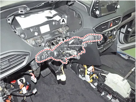
| 4. |
Disconnect the multifunction switch connector (A).
|
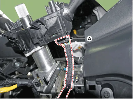
| 5. |
Loosen the screws (2EA) and then remove the multifunction switch assembly
(A).
|
| Installation |
| 1. |
Install the multifunction switch.
|
| 2. |
Install the clock spring and steering wheel.
|
| 3. |
Install the steering column upper and lower shrouds.
|
| 4. |
Install the steering wheel.
|
| Inspection |
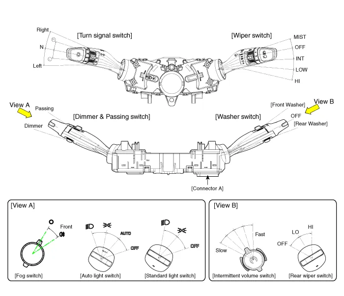
Multifunction Switch Inspection
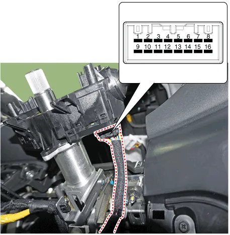
| 1. |
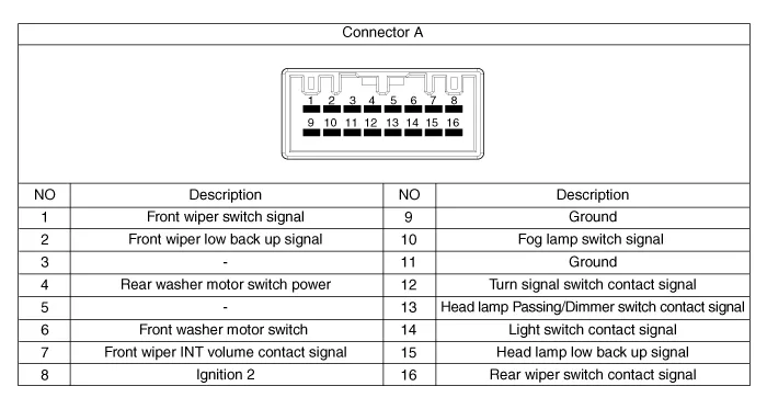
Check for continuity between the terminals in each switch position as
shown below.
|
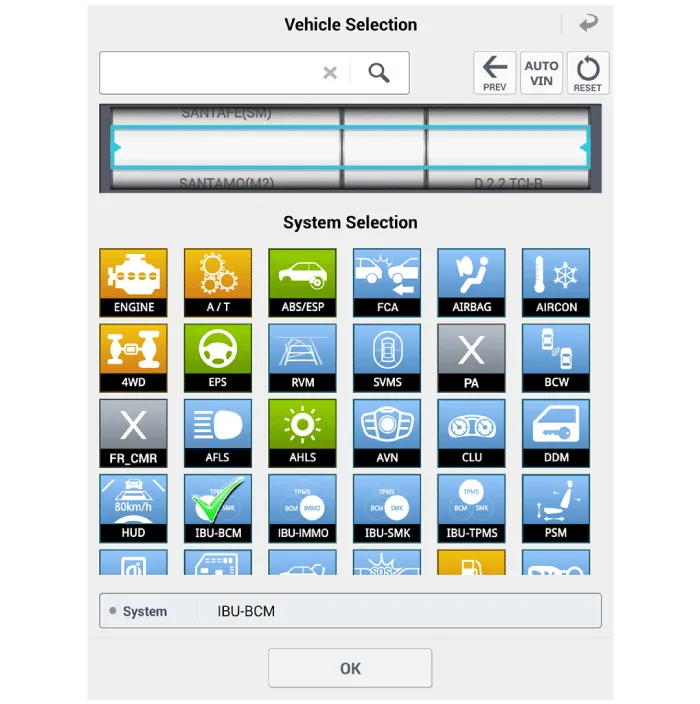
Inspection (With Diagnostic Tool)
| 1. |
In the body electrical system, failure can be quickly diagnosed by using
the vehicle diagnostic system (diagnostic tool).
The diagnostic system (diagnostic tool) provides the following information.
|
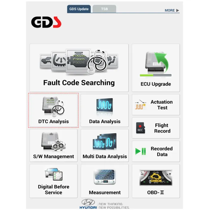
| 2. |
If diagnose the vehicle by diagnostic tool, select "DTC Analysis" and
"Vehicle".
|
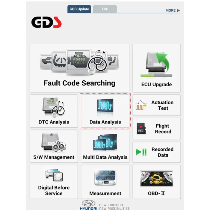
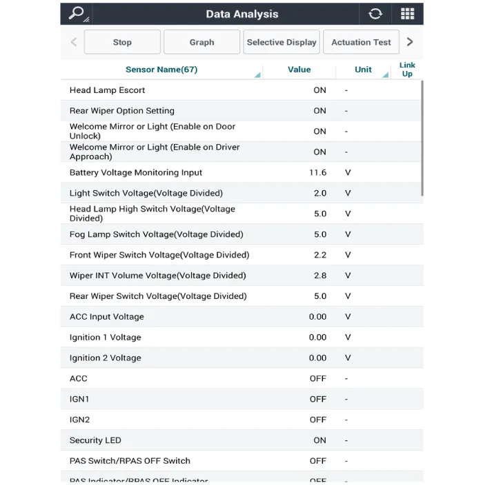
| 3. |
If check current status, select the "Data Analysis" and "Car model".
|
| 4. |
Select the 'IBU_BCM' to search the current state of the input/output
data.
|
Components and components location Component Location 1. Audio unit 2. Tweeter speaker 3. Roof antenna (Radio) 4.
Components and components location Component Location 1. Horn switch 2. Horn relay (Engine room compartment) 3. Horn (Low pitch) 4.
Other information:
Hyundai Santa Fe (TM) 2019-2023 Service and Repair Manual: Rear Glass Defogger
Components and components location Component Location 1. Rear glass defogger relay (Buil-in engine room relay box) 2. Rear glass defogger switch (Dual type) 3. Rear glass defogger switch (Manual type) 4.
Hyundai Santa Fe (TM) 2019-2023 Service and Repair Manual: Condenser. Components and components location
Categories
- Manuals Home
- Hyundai Santa Fe Owners Manual
- Hyundai Santa Fe Service Manual
- Engine Electrical System
- Engine Control/Fuel System
- Parking Brake System. Electronic Parking Brake (EPB)
- New on site
- Most important about car

Copyright © 2026 www.hsafe4.com - 0.0177