Hyundai Santa Fe (TM): Body Electrical System / Keyless Entry And Burglar Alarm
Description and operation
| Description |
|
B/A State |
Description |
||||||
|
DISARM |
|
||||||
|
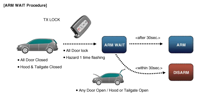
ARMWAIT |
|
|
B/A State |
Description |
||||||
|
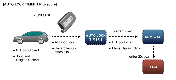
AUTO LOCK TIMER 1 |
|
|
B/A State |
Description |
||||||||
|
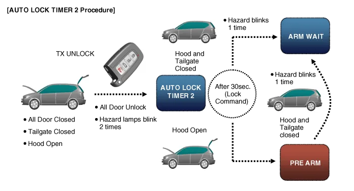
AUTO LOCK TIMER 2 |
|
|
B/A State |
Description |
||||||||||||
|
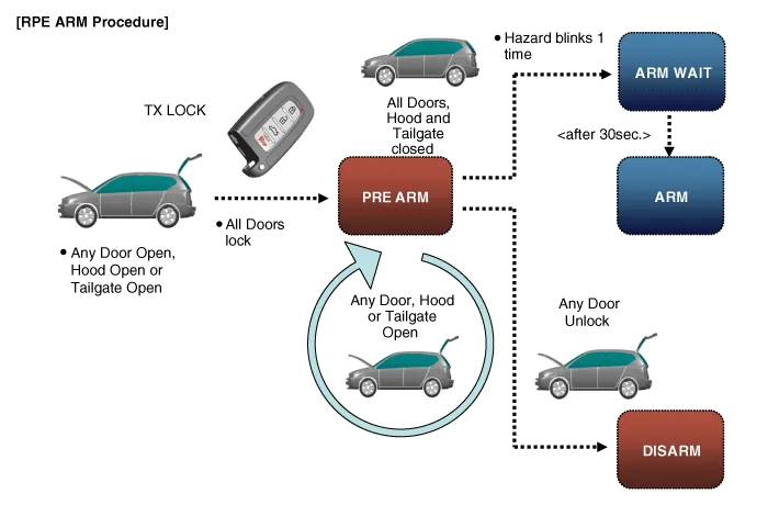
PRE ARM |
|
|
B/A State |
Description |
||||||
|
RE ARM |
|
|
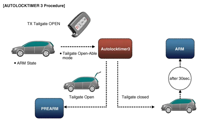
B/A State |
Description |
||||||||||
|
AUTOLOCK TIMER3 |
|
Components and components location
| Component Location |
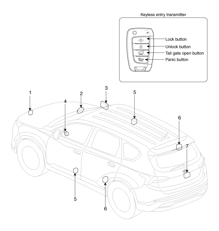
| 1. Hood switch 2. Burglar horn 3. Intergrated Body Control Unit (IBU) 4. Key warning switch |
5. Front door
lock actuator & switch 6. Rear door lock actuator & switch 7. Tailgate open switch |
Specifications
| Specification |
|
Item |
Specification |
|
Power source |
3V |
|
Operating temperature |
-20°C to +60°C (-4°F to- +140°F) |
|
RF Modulation |
FSK |
|
LF Modulation |
ASK |
|
RF frequency |
433.92MHz |
|
Battery |
CR2032 |
|
Transmissible distance |
10m or more |
|
Life of battery |
2years or more (at 20 times per day) |
|
Button number |
4 |
|
Function |
Door lock |
|
Door unlock |
|
|
Tailgate unlock |
|
|
Panic |
Repair procedures
| Inspection |
| 1. |
Remove the front door trim.
(Refer to Body - "Front Door Trim")
|
| 2. |
Remove the front door module.
(Refer to Body - "Front Door Module")
|
| 3. |
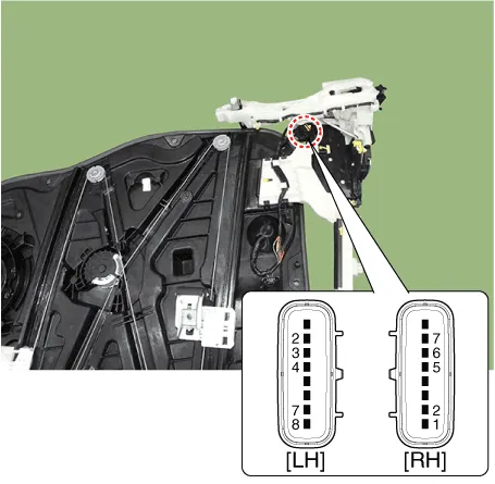
Disconnect the connectors from the actuator.
|
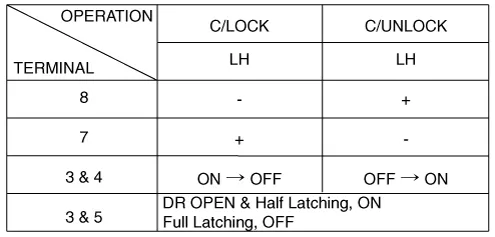
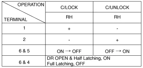
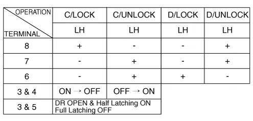
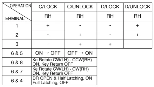
| 4. |
Check actuator operation by connecting power and ground according to
the table.
[Dead Lock]
[Central Lock]
[Central Lock]
[Dead Lock]
Driver
Passenger
|
| 1. |
Remove the rear door trim.
(Refer to Body - "Rear Door Trim")
|
| 2. |
Remove the rear door module.
(Refer to Body - "Rear Door Module")
|
| 3. |
Disconnect the connectors from the actuator.
|
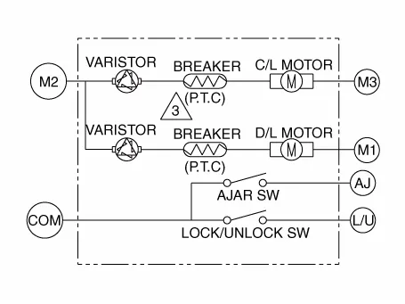
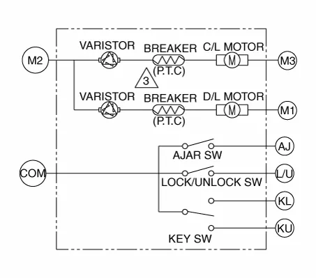
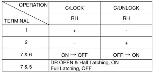
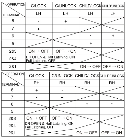
| 4. |
Check actuator operation by connecting power and ground according to
the table.
[Central Lock]
[Dead Lock]
[Child Lock]
|


| 1. |
Remove the tailgate trim.
(Refer to Body - "Tailgate Trim")
|
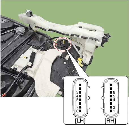
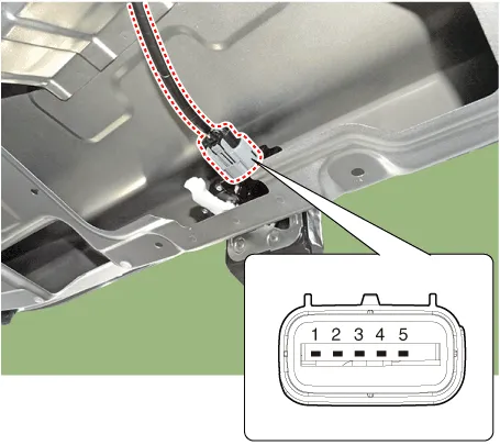
| 2. |
Disconnect the 4P connector from the actuator.
|
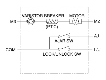
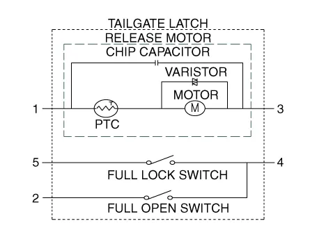
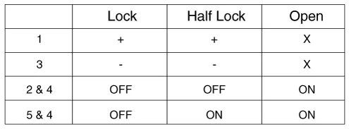
| 3. |
Check actuator operation by connecting power and ground according to
the table.
|
| 1. |
Disconnect the connector and bolts from the hood switch.
|
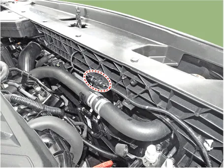
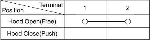
| 2. |
Check for continuity between the terminals and ground according to the
table.
|
Removal Interior 1 Antenna Take care not to scratch the crash pad and related parts.
Description and operation Description Body Control Module Controls The Followings – Wiper & Washer Control – Defroster Control – Driving Control – Tailgate Control – Window Control – Interior Control – Exterior Control – Panic alarm Control – MTS – Flasher output Control – Door lock/unlock Control – Burglar alarm Control – Remote start Control – UMS(User Mode Setting) Control – Gateway/ Diagnosis Integrated Body Control Unit (IBU) Integrated body control unit has integrated several functions including body control module (IBU), smart key unit (SMK), and tire pressure monitoring system (TPMS).
Other information:
Hyundai Santa Fe (TM) 2019-2023 Service and Repair Manual: Power Tailgate Module
Description and operation Description Power tailgate is an electro-mechanical system designed to provide power opening and closing of the tailgate through the push of a button of a remote key (fob), console switch, inner switch or an outside handle switch of the tailgate.
Hyundai Santa Fe (TM) 2019-2023 Service and Repair Manual: Repair procedures
Refrigerant System Service Basics (R-134a) Refrigerant Recovery Use only service equipment that is U.L-listed and is certified to meet the requirements of SAE J2210 to remove HFC-134a(R-134a) from the air conditioning system.
Categories
- Manuals Home
- Hyundai Santa Fe Owners Manual
- Hyundai Santa Fe Service Manual
- Engine Electrical System
- LCD Display
- Troubleshooting
- New on site
- Most important about car
