Hyundai Santa Fe (TM): Indicators And Gauges / Instrument Cluster. Repair procedures
Hyundai Santa Fe (TM) 2019-2023 Service and Repair Manual / Body Electrical System / Indicators And Gauges / Instrument Cluster. Repair procedures
| Removal |
| 1. |
Disconnect the negative (-) battery terminal.
|
| 2. |
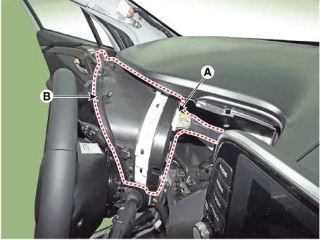
Remove the cluster fascia panel (A).
(Refer to Body - "Cluster Fascia Panel")
|
| 3. |
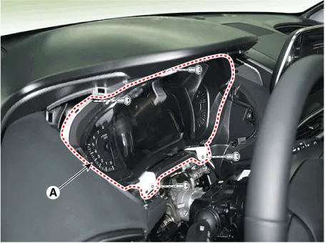
Remove the cluster (A) from the housing after removing 2 screws.
|
| 4. |
Disconnect the cluster connecter (A) and then remove the cluster (B).
|
| Installation |
| 1. |
Connect the cluster connector.
|
| 2. |
Install the cluster assembly.
|
| 3. |
Install the cluster facia panel.
|
| 4. |
Connect the negative (-) battery terminal.
|

| Inspection |
| 1. |
Check point (Warning indicator)
|


| 2. |
Check point (Gauge)
|
Diagnosis with Diagnostic Tool
| 1. |
In the body electrical system, failure can be quickly diagnosed by using
the vehicle diagnostic system.
The diagnostic system provides the following information.
|
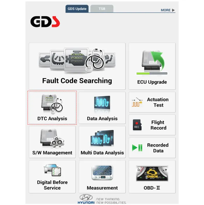
| 2. |
If diagnose the vehicle by diagnostic tool, select "DTC Analysis" and
"Vehicle".
|
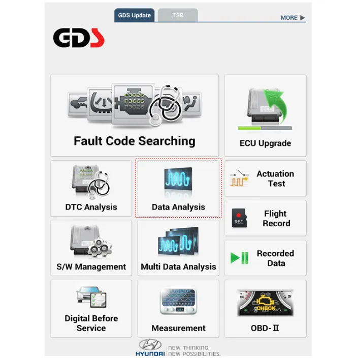
| 3. |
If check current status, select the "Data Analysis" and "Car model".
|
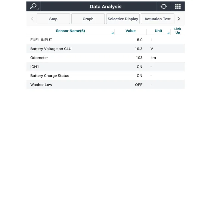
| 4. |
Select the 'CLU' to search the current state of the input/output data.
|

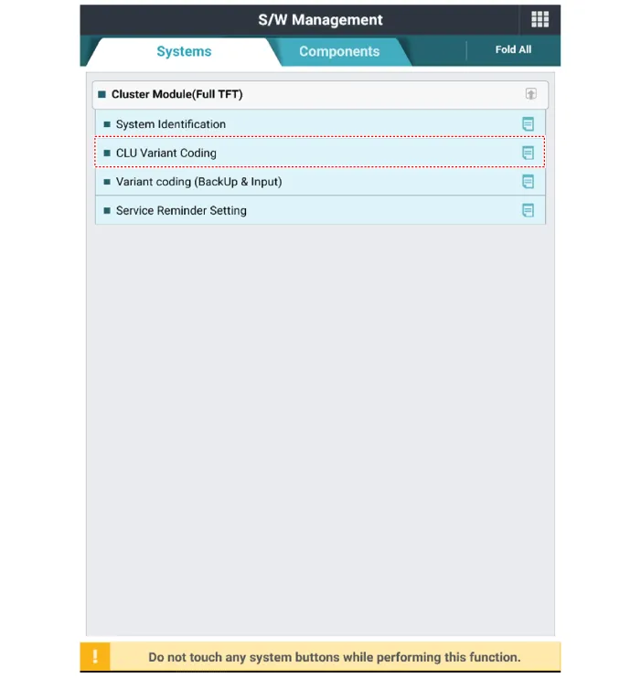
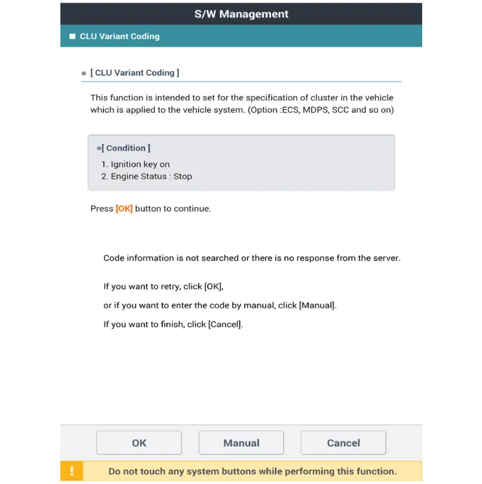
CLU Variant Coding
As we have more options (ESC, TPMS, SCC, etc.) in the car, the dashboard now
have more information to display depending on the chosen options.
For this reason, we need to learn which options the current vehicle when we
replace the dashboard.
To address this issue, a course of learning based on the option required for
the vehicle when replacing the dashboard should be carried out.
This is called Variant Coding.
| 1. |
Connect the cable of diagnostic tool to the data link connector in driver
side crash pad lower panel.
|
| 2. |
Select the 'S/W Management' and 'Car model'.
|

| 3. |
Select the 'Cluster Module' and 'CLU Variant Coding'.
|
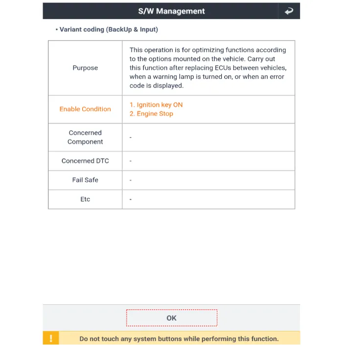
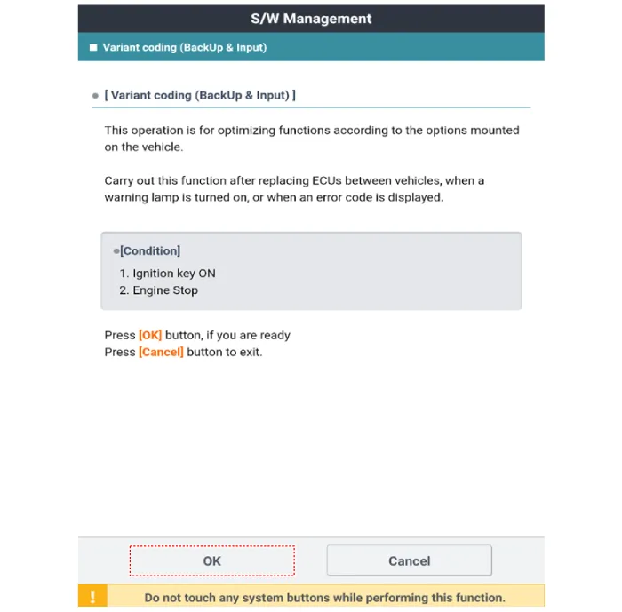
Variant Coding (BackUP & Input)
|
| 1. |
Back up the variable coding value before replacing the cluster.
|
| 2. |
Connect the cable of diagnostic tool to the data link connector in driver
side crash pad lower panel.
|
| 3. |
Select the 'S/W Management' and 'Car model'.
|
| 4. |
Select the 'Variant coding (Backup & Input).
|

| 5. |
After checking purpose and enable condition, press the ‘OK’ button.
|
| 6. |
Press the ‘OK’ button.
|
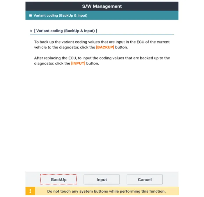
| 7. |
Select ‘BackUP’ to back up the variable coding value before replacing
the cluster.
|
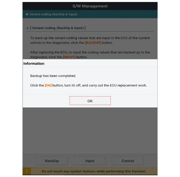
| 8. |
When the ‘Backup’ operation is completed, press the ‘OK’ button.
|
| 9. |
Replacement the new instrument cluster.
(Refer to Body Electrical System - "Instrument Cluster")
|
| 10. |
Connect the cable of diagnostic tool to the data link connector in driver
side crash pad lower panel.
|
| 11. |
Select the 'S/W Management' and 'Car model'.
|
| 12. |
Select the 'Variant coding (Backup & Input).
|
| 13. |
After checking purpose and enable condition, press the ‘OK’ button.
|
| 14. |
Press the ‘OK’ button.
|
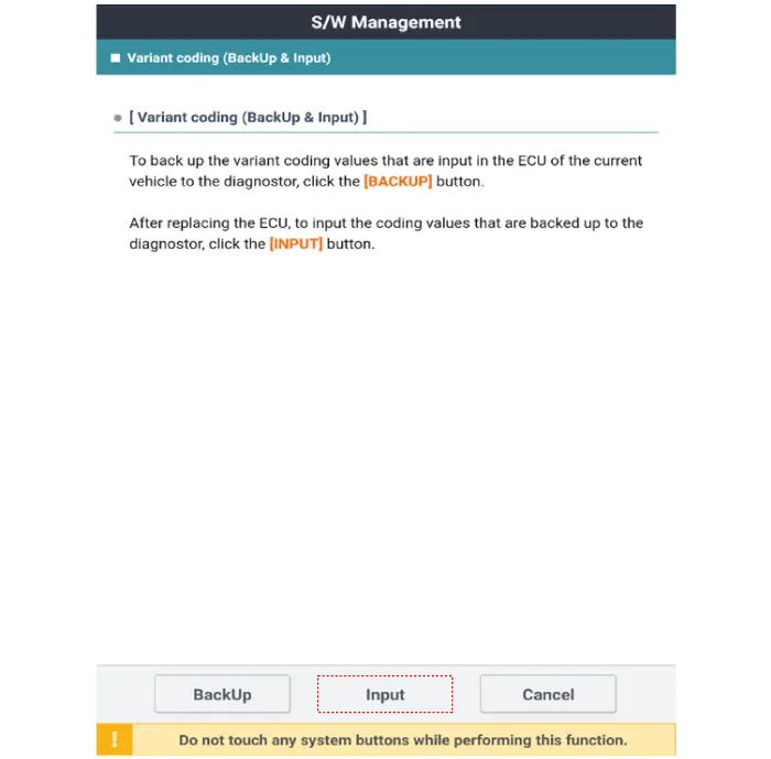
| 15. |
Select ‘Input’ to input the coding values.
|
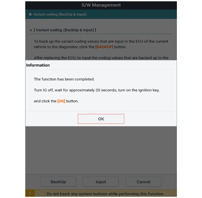
| 16. |
When the ‘Input’ operation is completed, press the ‘OK’ button.
|
Circuit Diagram MONO TFT LCD 3.5 Inch TFT LCD 4.2 Inch Color 12.3 Inch
Other information:
Hyundai Santa Fe (TM) 2019-2023 Service and Repair Manual: Components and components location
Hyundai Santa Fe (TM) 2019-2023 Service and Repair Manual: Ultrasonic Sensor. Repair procedures
Removal 1. Disconnect the negative (-) battery terminal. 2. Remove the front/rear bumper. (Refer to Body - "Front Bumper Cover") (Refer to Body - "Rear Bumper Cover") 3.
Categories
- Manuals Home
- Hyundai Santa Fe Owners Manual
- Hyundai Santa Fe Service Manual
- Fender Garnish. Repair procedures
- Front Wiper Motor. Components and components location
- General Information
- New on site
- Most important about car

Copyright © 2025 www.hsafe4.com - 0.0144