Hyundai Santa Fe (TM): Body Electrical System / Power Door Locks
Components and components location
| Component Location |
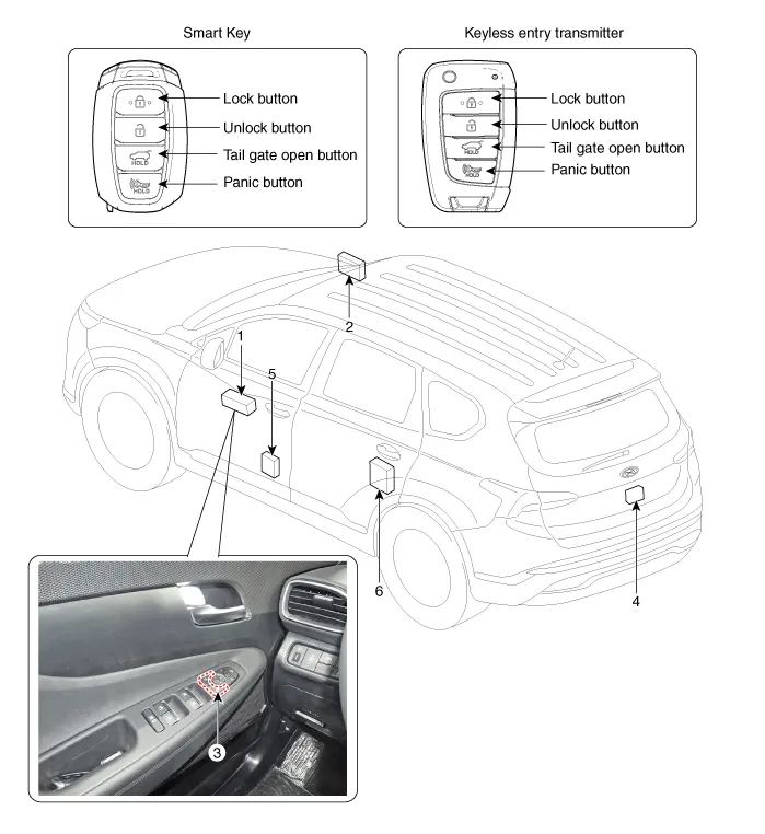
| 1. Driver power
window main switch 2. IBU (Integrated Body Control Unit) 3. Door lock switch |
4. Tailgate lock
actuator & switch 5. Front door lock actuator & switch 6. Rear door lock actuator & switch |
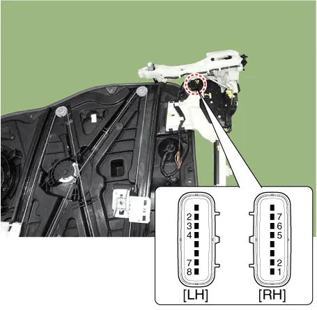
Power Door Lock Actuators. Repair procedures
| Inspection |
| 1. |
Remove the front door trim.
(Refer to Body - "Front Door Trim")
|
| 2. |
Remove the front door module.
(Refer to Body - "Front Door Module")
|
| 3. |
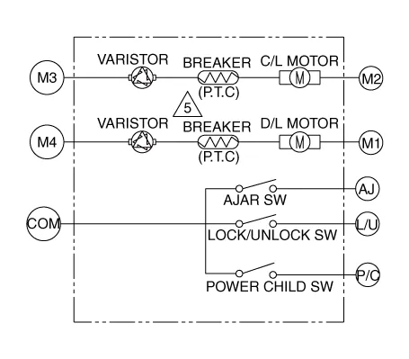
Disconnect the connectors from the actuator.
|
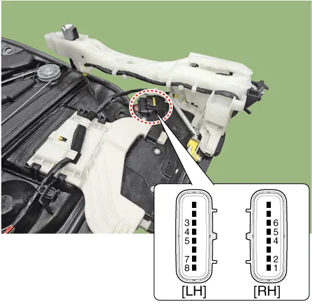
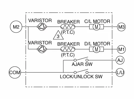
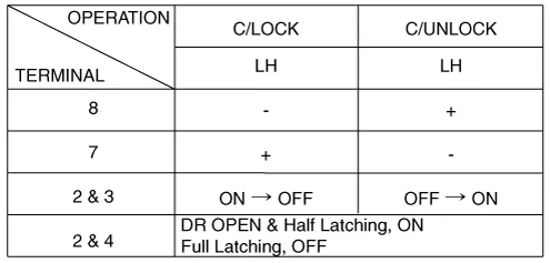
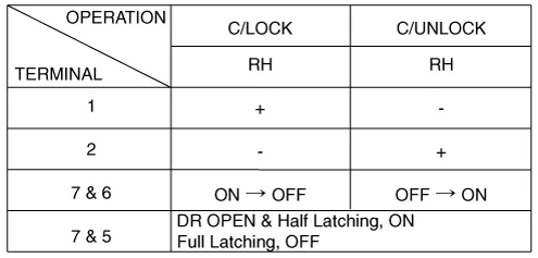
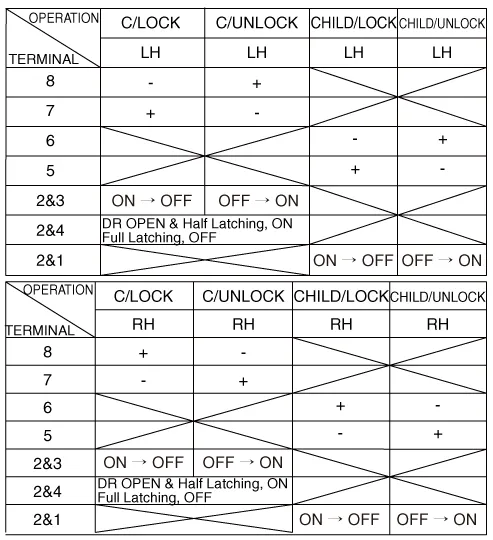
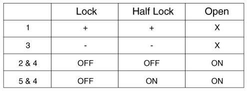
| 4. |
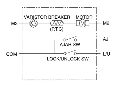
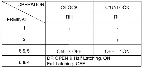
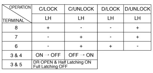
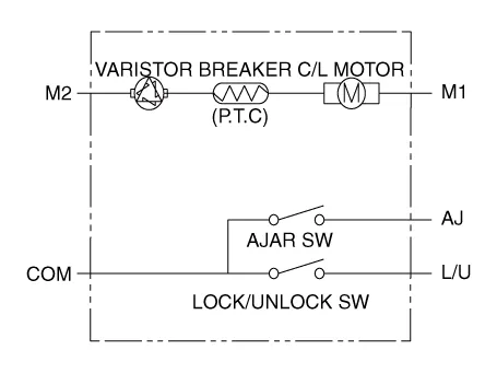
Check actuator operation by connecting power and ground according to
the table.
[Dead Lock]
[Central Lock]
[Central Lock]
[Dead Lock]
Driver
Passenger
|

| 1. |
Remove the rear door trim.
(Refer to Body - "Rear Door Trim")
|
| 2. |
Remove the rear door module.
(Refer to Body - "Rear Door Module")
|
| 3. |
Disconnect the connectors from the actuator.
|
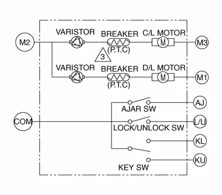
| 4. |
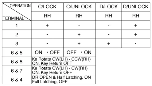
Check actuator operation by connecting power and ground according to
the table.
[Central Lock]
[Dead Lock]
[Child Lock]
|
| 1. |
Remove the tailgate trim.
(Refer to Body - "Tailgate Trim")
|
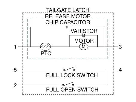
| 2. |
Disconnect the 4P connector from the actuator.
|
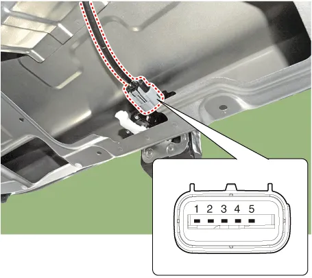
| 3. |
Check actuator operation by connecting power and ground according to
the table.
|
| 1. |
Disconnect the connector and bolts from the hood switch.
|
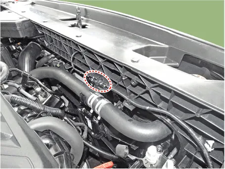
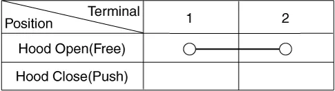
| 2. |
Check for continuity between the terminals and ground according to the
table.
|
Power Door Lock Switch. Repair procedures
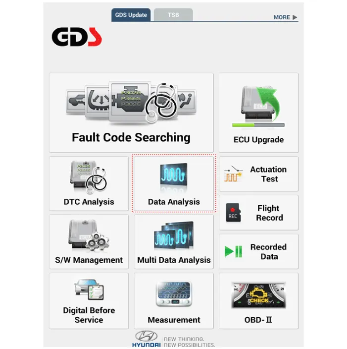
| Diagnosis with Diagnostic Tool |
| 1. |
In the body electrical system, failure can be quickly diagnosed by using
the vehicle diagnostic system.
The diagnostic system provides the following information.
|
| 2. |
If diagnose the vehicle by diagnostic tool, select "DTC Analysis" and
"Vehicle".
|
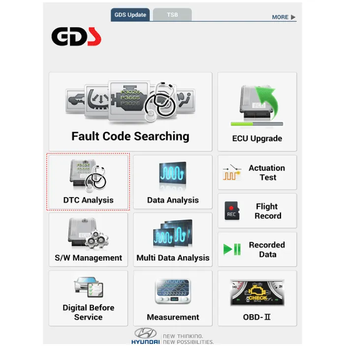
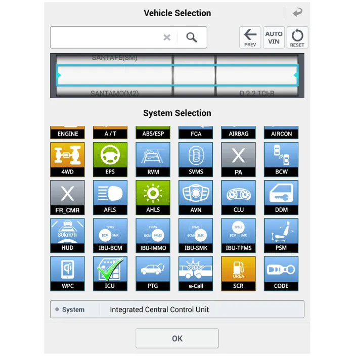
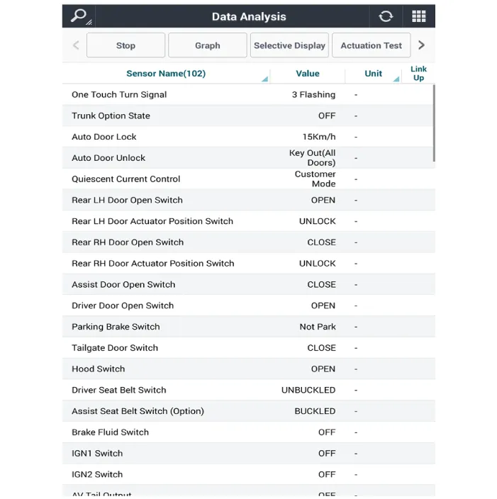
| 3. |
If check current status, select the "Data Analysis" and "Car model".
|
| 4. |
Select the 'ICU' to search the current state of the input/output data.
|
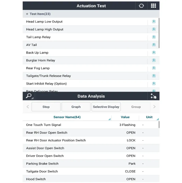
| 5. |
To forcibly actuate the input value of the module to be checked, select
option 'Actuation Test'.
|
| Removal |
| 1. |
Disconnect the negative (-) battery terminal.
|
| 2. |
Remove the front door trim.
(Refer to Body - "Front Door Trim")
|
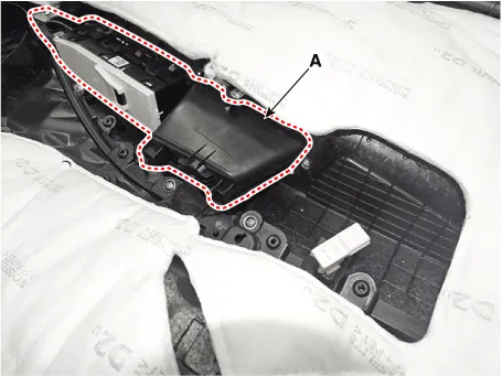
| 3. |
Remove the power window bezzel assembl (A) after loosening the mounting
screws.
|
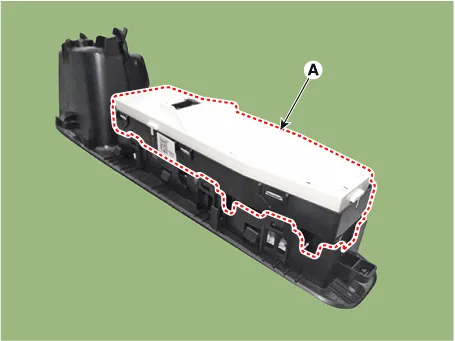
| 4. |
Remove the power window switch assembly (A) after loosening the mounting
screws.
|
| Installation |
| 1. |
Install the power window switch assembly.
|
| 2. |
Install the front door trim after connecting the connector.
|
Troubleshooting Troubleshooting Symptom Possible cause Remedy Speedometer does not operate Cluster fuse (10A) blown Check for short and replace fuse Speedometer faulty Check speedometer CAN line faulty Check the EMS Wiring or ground faulty Repair if necessary Tachometer does not operate Cluster fuse (10A) blown Check for short and replace fuse Tachometer faulty Check tachometer CAN line faulty Check the EMS Wiring or ground faulty Repair if necessary Fuel gauge does not operate Cluster fuse (10A) blown Check for short and replace fuse Fuel gauge faulty Check gauge Fuel sender faulty Check fuel sender Wiring or ground faulty Repair if necessary Low fuel warning lamp does not light up Cluster fuse (10A) blown Check for short and replace fuse Bulb burned out Replace bulb Fuel sender faulty Check fuel sender Wiring or ground faulty Repair if necessary Water temperature gauge does not operate Cluster fuse (10A) blown Check for short and replace fuse Water temperature gauge faulty Check gauge Water temperature sender faulty Check sender CAN line faulty Check the EMS Wiring or ground faulty Repair if necessary Oil pressure warning lamp does not light up Cluster fuse (10A) blown Check for short and replace fuse Bulb burned out Replace bulb Oil pressure switch faulty Check switch Wiring or ground faulty Repair if necessary Parking brake warning lamp does not light up Cluster fuse (10A) blown Check for short and replace fuse Bulb burned out Replace bulb Brake fluid level warning switch faulty Check switch Parking brake switch faulty Check switch Wiring or ground faulty Repair if necessary Open door warning lamp and tailgate warning lamp do not light up Memory fuse (15A) blown Check for short and replace fuse Bulb burned out Replace bulb Door switch faulty Check switch Wiring or ground faulty Repair if necessary Seat belt warning lamp does not light up Cluster fuse (10A) blown Check for short and replace fuse Bulb burned out Replace bulb Seat belt switch faulty Check switch Wiring or ground faulty Repair if necessary Speedometer and odometer does not operate CAN line faulty Check the ABS ECU Wheel speed sensor faulty Check the wheel speed sensor Instrument Cluster.
Components and components location Component Location 1. Power door mirror 2. Power door mirror switch 3. Power folding mirror switch Power Door Mirror Switch.
Other information:
Hyundai Santa Fe (TM) 2019-2023 Service and Repair Manual: Integrated Body Control Unit (IBU)
Description and operation Description Body Control Module Controls The Followings – Wiper & Washer Control – Defroster Control – Driving Control – Tailgate Control – Window Contr
Hyundai Santa Fe (TM) 2019-2023 Service and Repair Manual: Compressor. Description and operation
Description The compressor is the power unit of the A/C system. It is located on the side of engine block and driven by a V-belt of the engine. The compressor changes low pressure and low temperature refrigerant gas into high pressure and high temperature refrigerant gas.
Categories
- Manuals Home
- Hyundai Santa Fe Owners Manual
- Hyundai Santa Fe Service Manual
- Parking Brake System. Electronic Parking Brake (EPB)
- Engine Electrical System
- Blower
- New on site
- Most important about car
