Hyundai Santa Fe: Indicators And Gauges / Instrument Cluster. Description and operation
Hyundai Santa Fe (TM) 2019-2025 Service Manual / Body Electrical System / Indicators And Gauges / Instrument Cluster. Description and operation
| Description |
Communication Network Diagram
|
Abbreviation |
Explanation |
|
IBU |
Interated Body Control Unit |
|
DDM |
Driver Door Module |
|
PTGM |
Power Tail Gate Module |
|
ICU |
Interated Control Unit |
|
PCU |
Powertrain Control Unit |
|
ECU |
Engine Control Unit |
|
CLU |
Cluster |
|
MDPS |
Moter Driven Power Steering |
|
SVM |
Sorround View Monitor |
|
ACU |
Airbag Control Unit |
|
VDC |
Vehicle Dynamic Control |
|
SCC |
Smart Cruise Control |
|
DBL |
Dynamic banding Light |
|
LKA |
Lane Keeping Assist |
|
BCW |
Blind-Spot Collision Warning |
|
RVM |
Rear View Monitor |
|
SAS |
Steering Angle Sensor |
|
HUD |
Head up Display |
|
TCU |
Transmission Control Unit |
|
MTC |
Temp Control |
|
DATC |
Dual Automatic Temp Control |
|
4WD |
Four Wheel Drive |
|
F/PUMP |
Fuel Pump Control Module |
|
V/PUMP |
Vacuum Pump |
|
OCS |
Occupant Classification System |
|
WPC |
Wireless Power Chager |
|
IMS |
Integrated Memory System |
|
AMP |
Amplifier |
|
AVN |
Head Unit (Audio / AVN) |
|
HUD |
Head Up Display |

 Instrument Cluster. Components and components location
Components
MONO TFT LCD 3.5 Inch
TFT LCD 4.2 Inch
Color 12.3 Inch
Connector Pin Information
No...
Other information:
Hyundai Santa Fe (TM) 2019-2025 Owner's Manual: System malfunction and limitations
System malfunction When Highway Driving Assist or Highway Lane Change function is not working properly, the ‘Check Highway Driving Assist (HDA) system’ (or 'Check HDA (Motorway Driving Assist) system') warning message will appear, and the warning light will illuminate on the cluster...
Hyundai Santa Fe (TM) 2019-2025 Owner's Manual: System operation
Warning and control Lane Following Assist If the vehicle ahead and/or both lane markings are detected and your vehicle speed is below 110 mph (180 km/h), the green indicator light will illuminate on the cluster, and the system will help center the vehicle in the lane by assisting the steering wheel...
Categories
- Manuals Home
- 4th Generation Santa Fe Owners Manual
- 4th Generation Santa Fe Service Manual
- Electronic Parking Brake (EPB) warning light. AUTO HOLD indicator light
- Troubleshooting
- Gauges and meters
- New on site
- Most important about car
Air bag - supplemental restraint system
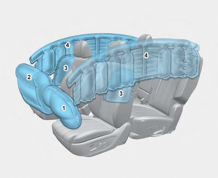
1. Driver’s front air bag
2. Passenger’s front air bag
3. Side air bag
4. Curtain air bag
The vehicles are equipped with a Supplemental Air Bag System for the driver’s seat and front passenger’s seats.
The front air bags are designed to supplement the three-point seat belts. For these air bags to provide protection, the seat belts must be worn at all times when driving.

Copyright © 2025 www.hsafe4.com