Hyundai Santa Fe (TM): Body Electrical System / Horn
Components and components location
| Component Location |
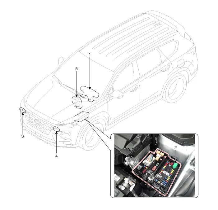
| 1. Horn switch 2. Horn relay (Engine room compartment) 3. Horn (Low pitch) |
4. Horn (High
pitch) 5. Clock spring |
Repair procedures
| Removal |
| 1. |
Remove the front bumper cover.
(Refer to Body - "Front Bumper Cover"
|
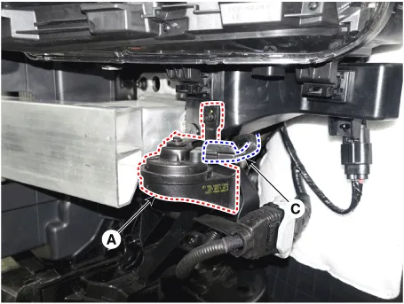
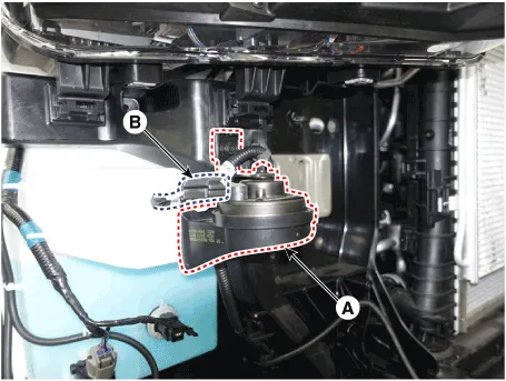
| 2. |
Remove the bolts and disconnect the horn connectors (C), then remove
the high pitch horn (B) and low pitch horn (A).
|
| Installation |
| 1. |
Install the horns after connecting the horn connectors.
|
| 2. |
Install the front bumper cover.
|
| Inspection |
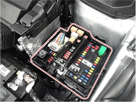
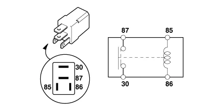
| 1. |
Remove the horn relay (A) from the engine room relay box.
|
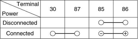
| 2. |
There should be continuity between the No.30 and No.87 terminals when
power and ground are connected to the No.85 and No.86 terminals.
|
| 3. |
There should be no continuity between the No.30 and No.87 terminals
when power is disconnected.
|
Components and components location Component 1. Steering column 2. Multifunction switch 3. Screw 4. Clock spring Specifications Specifications Items Specifications Rated voltage DC 12V Operating temperature range -22 to +176°F (-30°C to +80°C) Rated load Dimmer & passing switch High : 0.
Description and operation Description AVN system The AVN system has improved information search and easiness of manipulation for the driver by simplifying the system operation experience and unifying the display of the user information such as multimedia and car information.
Other information:
Hyundai Santa Fe (TM) 2019-2023 Service and Repair Manual: Power Door Locks
Components and components location Component Location 1. Driver power window main switch 2. IBU (Integrated Body Control Unit) 3. Door lock switch 4. Tailgate lock actuator & switch 5. Front door lock actuator & switch 6.
Hyundai Santa Fe (TM) 2019-2023 Service and Repair Manual: Photo Sensor. Description and operation
Description The photo sensor is located at the center of the defrost nozzles. The photo sensor contains a photovoltaic (sensitive to sunlight) diode. The solar radiation received by its light receiving portion, generates an electromotive force in proportion to the amount of radiation received which is transferred to th
Categories
- Manuals Home
- Hyundai Santa Fe Owners Manual
- Hyundai Santa Fe Service Manual
- Automatic Transaxle System (SBC)
- Brake System
- Auto Hold. Warning messages
- New on site
- Most important about car
