
Hyundai Santa Fe (TM): ESP(Electronic Stability Program) System / ESP Control Module. Components and components location
| Components |
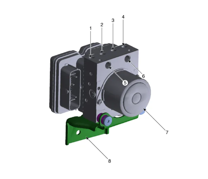
| 1. Front - right
(FR) 2. Rear - left (RL) 3. Rear - right (RR) 4. Front - left (FL) |
5. MC2 6. MC1 7. ESP control module (HECU) 8. Bracket |
Failure Diagnosis 1. In principle, ESP and TCS controls are prohibited in case of ABS failure. 2.
Removal 1. Turn ignition switch OFF and disconnect the negative (-) battery cable. 2. Pull up the lock of the HECU connector and then disconnect the connector (A).
Other information:
Hyundai Santa Fe (TM) 2019-2023 Service and Repair Manual: Photo Sensor. Description and operation
Description The photo sensor is located at the center of the defrost nozzles. The photo sensor contains a photovoltaic (sensitive to sunlight) diode. The solar radiation received by its light receiving portion, generates an electromotive force in proportion to the amount of radiation received which is transferred to th
Hyundai Santa Fe (TM) 2019-2023 Service and Repair Manual: Auto Defogging Sensor. Repair procedures
Inspection To inspect and diagnose the sensor, refer to Self-Diagnosis procedure and DTC guide. Replacement 1. Disconnect the negative (-) battery terminal. 2. Remove the rain sensor inner cover (A) and rain sensor cover (B).
Categories
- Manuals Home
- Hyundai Santa Fe Owners Manual
- Hyundai Santa Fe Service Manual
- Identification Numbers
- Engine Control/Fuel System
- Fuel Delivery System
- New on site
- Most important about car
