Hyundai Santa Fe (TM): Engine Control System / Components and components location
| Components Location |
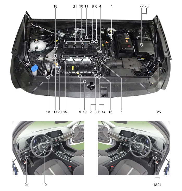
| 1. ECM (Engine
Control Module) 2. Manifold Absolute Pressure Sensor (MAPS) 3. Intake Air Temperature Sensor (IATS) 4. Engine Coolant Temperature Sensor (ECTS) 5. Throttle Position Sensor (TPS) 6. Crankshaft Position Sensor (CKPS) 7. Camshaft Position Sensor (CMPS) [Bank 1 / Intake] 8. Camshaft Position Sensor (CMPS) [Bank 1 / Exhaust] 9. Knock Sensor (KS) 10. Heated Oxygen Sensor (HO2S) [Bank 1 / Sensor 1] 11. Heated Oxygen Sensor (HO2S) [Bank 1 / Sensor 2] 12. Accelerator Position Sensor (APS) 13. A/C Pressure Transducer (APT) |
14. ETC Motor
15. Injector 16. Purge Control Solenoid Valve (PCSV) 17. Variable Force Solenoid (VFS) [Bank 1 / Intake] 18. Variable Force Solenoid (VFS) [Bank 1 / Exhaust] 19. Variable Intake Solenoid (VIS) 20. Ignition Coil 21. Main Relay 22. Fuel Pump Relay 23. Data Link Connector (DLC) [16-Pin] 24. Multi-Purpose Check Connector [16 Pin] |
|
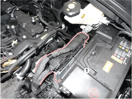
1. ECM (Engine Control Module) |
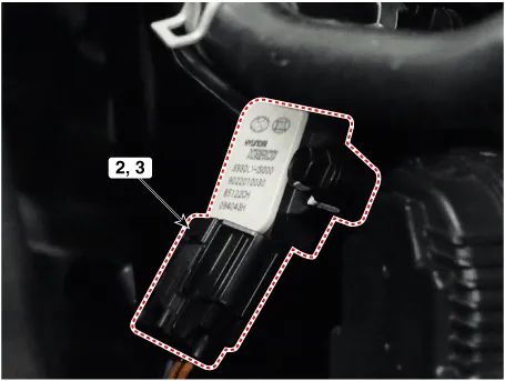
2. Manifold Absolute Pressure Sensor (MAPS) 3. Intake Air Temperature Sensor (IATS) |
|
|
|
|
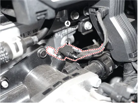
4. Engine Coolant Temperature Sensor (ECTS) |
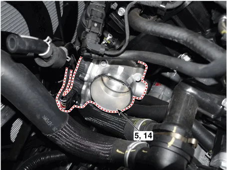
5. Throttle Position Sensor (TPS) [integrated into ETC Module] 14. ETC Motor [integrated into ETC Module] |
|
|
|
|
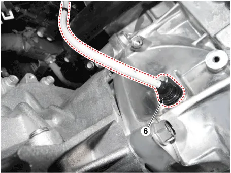
6. Crankshaft Position Sensor (CKPS) |
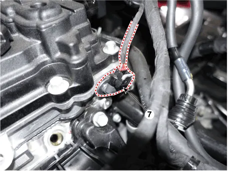
7. Camshaft Position Sensor (CMPS) [Bank 1 / Intake] |
|
|
|
|
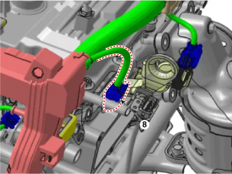
8. Camshaft Position Sensor (CMPS) [Bank 1 / Exhaust] |
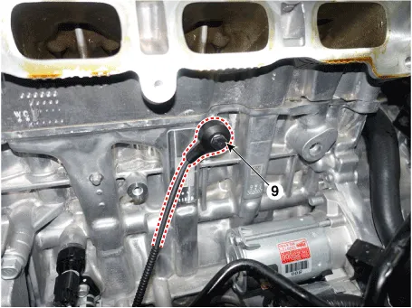
9. Knock Sensor (KS) |
|
|
|
|
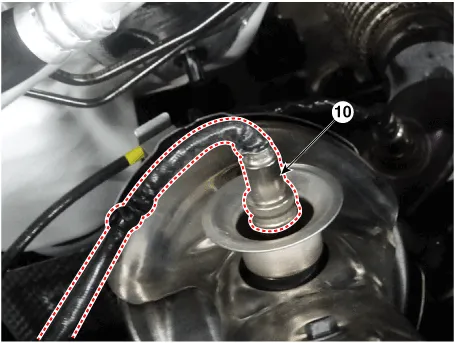
10. Heated Oxygen Sensor (HO2S) [Bank 1 / Sensor 1] |
11. Heated Oxygen Sensor (HO2S) [Bank 1 / Sensor 2] |
|
|
|
|
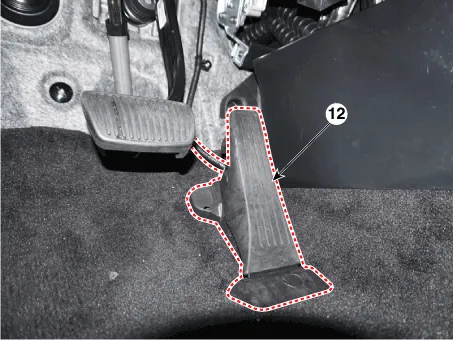
12. Accelerator Position Sensor (APS) |
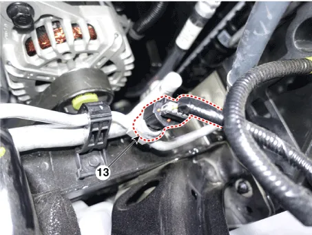
13. A/C Pressure Transducer (APT) |
|
|
|
|
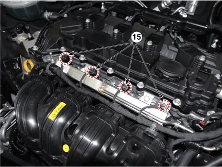
15. Injector |
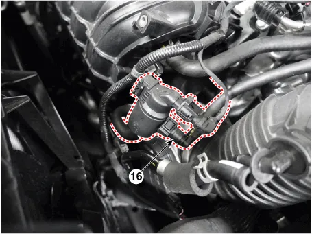
16. Purge Control Solenoid Valve (PCSV) |
|
|
|
|
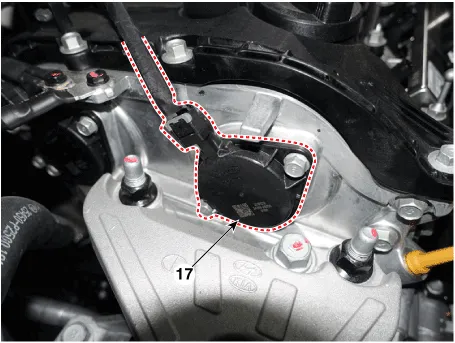
17. Variable Force Solenoid (VFS) [Bank 1 / Intake] |
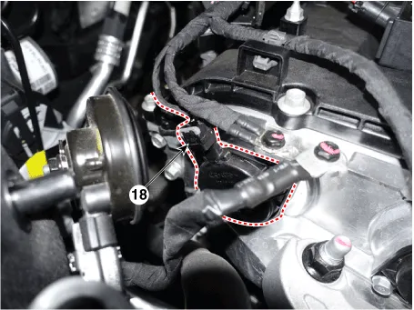
18. Variable Force Solenoid (VFS) [Bank 1 / Exhaust] |
|
|
|
|
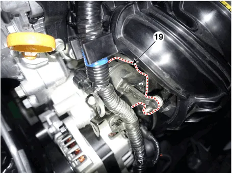
19. Variable Intake Solenoid (VIS) |
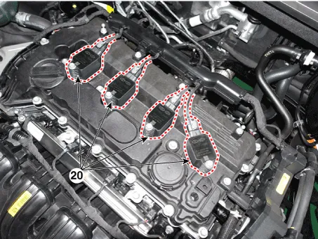
20. Ignition Coil |
|
|
|
|
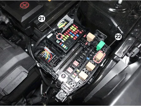
21. Main Relay 22. Fuel Pump Relay |
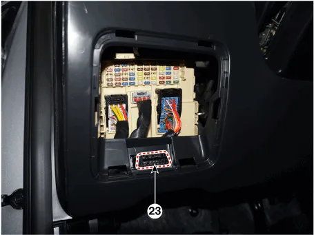
23. Data Link Connector (DLC) [16-Pin] |
|
|
|
|
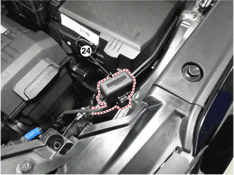
24. Multi-Purpose Check Connector [16 Pin] |
|
|
|
|

Description If the Gasoline Engine Control system components (sensors, ECM, injector, etc.) fail, interruption to the fuel supply or failure to supply the proper amount of fuel for various engine operating conditions will result.
ECM Terminal and Input/Output signal ECM Terminal Function Connector A Pin No Description Connected to 1 Power ground Chassis Ground 2 - - 3 - - 4 - - 5 - - 6 Fuel Sender Signal Fuel Sender 7 - - 8 - - 9 - - 10 - - 11 - - 12 - - 13 - - 14 - - 15 Stop Lamp Signal Stop Lamp 16 Brake Test Switch Brake Switch 17 18 - 19 - 20 Output Speed (Supply) ATM Solenoid Valve (Otput Speed) 21 Input Speed (Supply) ATM Solenoid Valve (Input Speed) 22 - - 23 - - 24 - - 25 - - 26 - - 27 [A/T] SOL.
Other information:
Hyundai Santa Fe (TM) 2019-2023 Service and Repair Manual: Specifications
Specifications Smart Key Unit Items Specification Rated voltage DC 12V Operating voltage DC 9 - 16V Operating temperature -22°F to 167°F (-30°C to- 75°C) Load Max.
Hyundai Santa Fe (TM) 2019-2023 Service and Repair Manual: Rear Glass Defogger
Components and components location Component Location 1. Rear glass defogger relay (Buil-in engine room relay box) 2. Rear glass defogger switch (Dual type) 3. Rear glass defogger switch (Manual type) 4.
Categories
- Manuals Home
- Hyundai Santa Fe Owners Manual
- Hyundai Santa Fe Service Manual
- Front Radar Unit. Repair procedures
- Parking Brake System. Electronic Parking Brake (EPB)
- LCD Display
- New on site
- Most important about car
