Hyundai Santa Fe (TM): Body (Interior and Exterior) / Body Side Molding
Rear Spoiler. Components and components location
| Component Location |
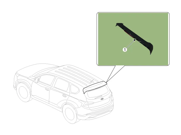
| 1. Rear Spoiler |
Rear Spoiler. Repair procedures
| Replacement |
|

|

| 1. |
Remove the tailgate upper trim.
(Refer to Tailgate - "Liftgate Trim")
|
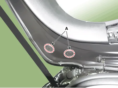
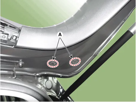
| 2. |
Remove the rear spoiler plug hole (A).
[LH]
[RH]
|
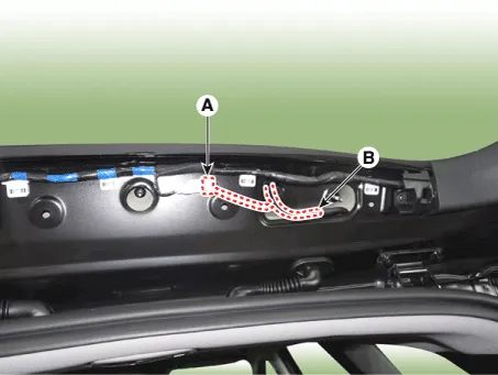
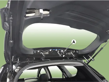
| 3. |
Separate the rear stop lamp connector (A) and rear washer nozzle (B).
|
| 4. |
Loosen the mounting nuts (A) and remove the rear spoiler (B).
|

| 5. |
To install, reverse the removal procedure.
|

Fender Garnish. Repair procedures
| Replacement |
|
|
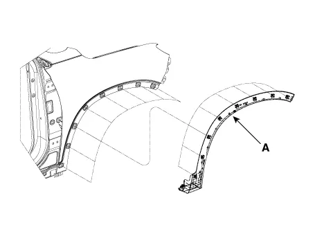
| 1. |
Using a screwdriver or remover, remove the fender garnish (A).
|
| 2. |
To install, reverse removal procedure.
|
Quarter Garnish. Repair procedures
| Replacement |
|
|
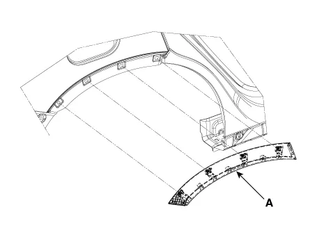
| 1. |
Using a screwdriver or remover, remove the quarter garnish (A).
|
| 2. |
To install, reverse removal procedure.
|
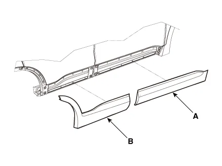
Side Sill Molding. Repair procedures
| Replacement |
|
|
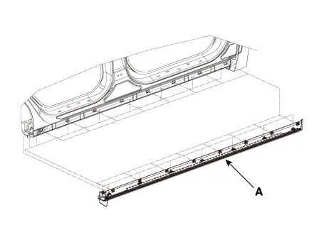
| 1. |
Using a remover, remove the side sill molding (A).
|
| 2. |
To install, reverse removal procedure.
|
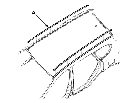
Roof Side Molding. Repair procedures
| Replacement |
|
|
| 1. |
Using a screwdriver or remover, remove the roof side molding (A).
|
| 2. |
To install, reverse removal procedure.
|
Roof Rack. Components and components location
| Components Location |
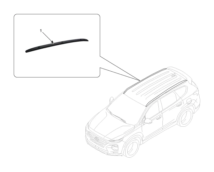
| 1. Roof rack
assembly |
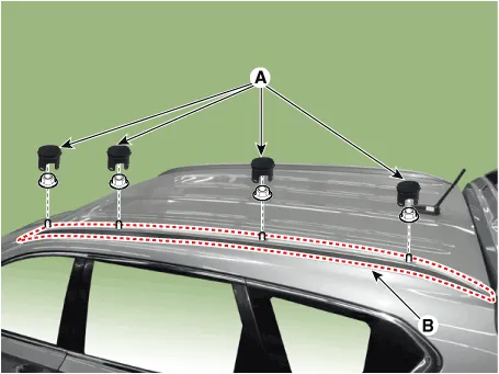
Roof Rack. Repair procedures
| Removal |
|
| 1. |
Remove the roof rack side cap (A).
|
| 2. |
Loosen the nuts and remove the roof rack assembly (B).
|
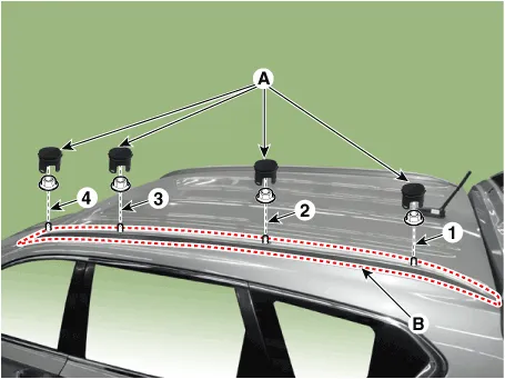
| Installation |
| 1. |
Install the roof rack assembly (B).
|
| 2. |
Install the roof rack side cap (A).
|
Front Wheel Guard. Repair procedures
| Replacement |
|
| 1. |
Remove the front tire.
|
| 2. |
Loosen the mounting clip,nuts and screws , and remove the front wheel
guard (A).
|
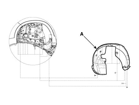
| 3. |
To install, reverse the removal procedure.
|
Rear Wheel Guard. Repair procedures
| Replacement |
|
| 1. |
Remove the rear tire.
|
| 2. |
Loosen the mounting clip and remove the rear wheel guard (A).
|
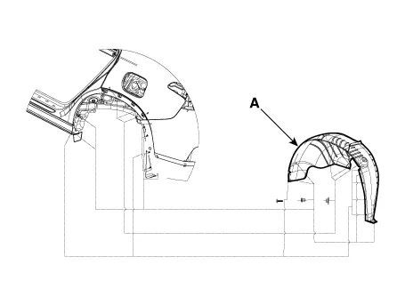
| 3. |
To install, reverse the removal procedure.
|
Door Garnish. Repair procedures
| Replacement |
|
| 1. |
Using a remover or screwdriver and remove the front door garnish (A)
and rear door garnish (B).
|
| 2. |
To install, reverse the removal procedure.
|
Components and components location Components 1. Rear door window glass 2. Rear door window glass run assembly 3.
Components and components location Component 1. Mechanism rail assembly 2. Center cover assembly 3. Roller blind motor 4.
Other information:
Hyundai Santa Fe (TM) 2019-2023 Service and Repair Manual: Seat Electrical
Components and components location Component Location 1. Lumber support motor (Vertical) 2. Lumbar support motor (Horizontal) 3. Reclining motor 4. Rear height motor 5. Front height motor 6. Slide motor 7.
Hyundai Santa Fe (TM) 2019-2023 Service and Repair Manual: Surround View Monitor (SVM)
Description and operation Description Surround View Monitor (SVM) is the system that allows video monitoring of 360 degrees around the vehicle. The system includes 4 ultra optical camera mounted around the vehicle (front, both sides, rear).
Categories
- Manuals Home
- Hyundai Santa Fe Owners Manual
- Hyundai Santa Fe Service Manual
- Front Radar Unit. Repair procedures
- Body Electrical System
- 4 Wheel Drive (4WD) System
- New on site
- Most important about car
