Hyundai Santa Fe (TM): Automatic Transaxle System / Automatic Transaxle. Repair procedures
| Removal |
|

| 1. |
Turn ignition switch OFF and disconnect the negative (-) battery cable.
|
| 2. |
Remove the air cleaner assembly and air duct.
(Refer to Engine Mechanical System - "Air Cleaner")
|
| 3. |
Remove the battery and battery tray.
(Refer to Engine Electrical System - "Battery")
|
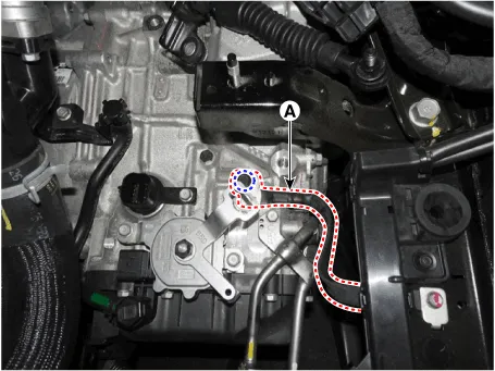
| 4. |
Loosen the bolts (B) and nut (A) and then separate the shift cable and
cable bracket (C) at the same time.
|
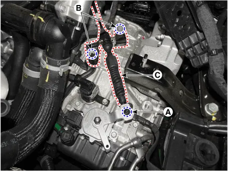
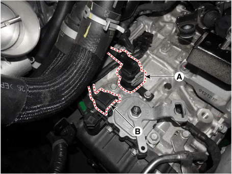
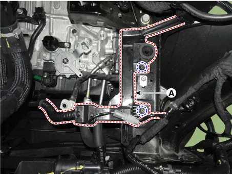
| 5. |
Dissconnect the main connector (A) and the position switch connector
(B).
|
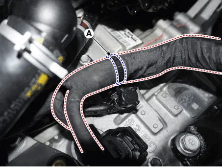
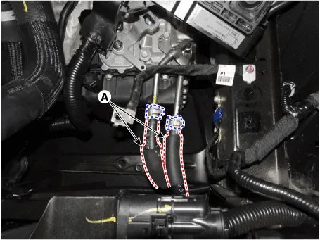
| 6. |
Separate the wiring clips (A).
|
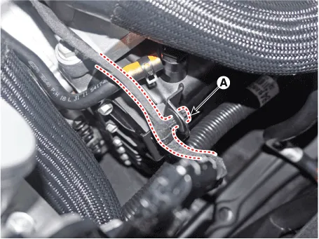
| 7. |
Remove the ground line (A).
|
| 8. |
Loosen the bolts and then separate the engine wiring (A).
|
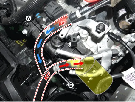
| 9. |
Separate the ATF cooler hose (A).
|
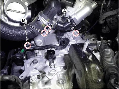
| 10. |
Loosen the transaxle upper mounting bolts (A) and the starter mounting
bolts (B).
|
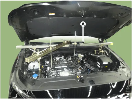
| 11. |
Assemble the engine support fixture use a service special tools .(Beam
SST No.: 09200 - 3N000 Adapter SST No.: 09200-2W000, Engine fixture
adapter (rear) SST No.: 09200-L1100, Engine fixture adapter (front)
SST No.: 09200-L1200)
|
| 12. |
Using the engine support fixture (A), hold the engine and transaxle
assembly safely.
|
| 13. |
Remove the front wheel guard. [LH]
(Refer to Body (Interior and Exterior) - "Front Wheel Guard")
|
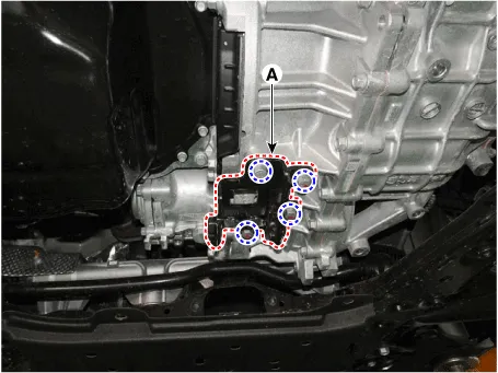
| 14. |
Loosen the transaxle bracket support mounting bolts (A).
|
| 15. |
Loosen the bolts and then removing the transaxle bracket (A).
|
| 16. |
Remove the under cover.
(Refer to Engine Mechanical System - "Engine Room Under Cover")
|
| 17. |
Remove the sub frame.
(Refer to Suspension System - "Sub Frame")
|
| 18. |
Remove the driveshaft assembly.
(Refer to Driveshaft and Axle - "Front Driveshaft")
|
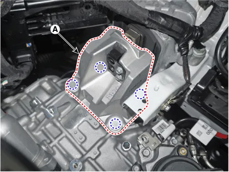
| 19. |
Loosen the bolts and then removing the roll rod support bracket (A).
|
| 20. |
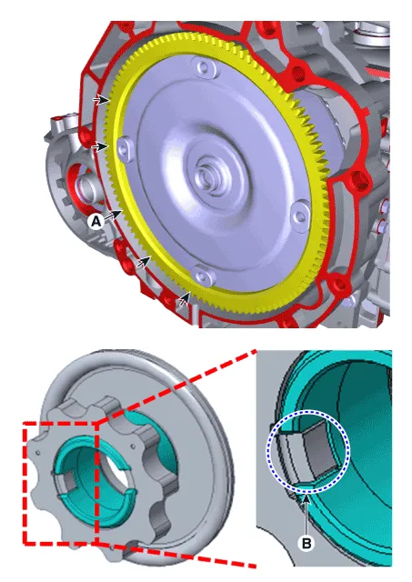
Remove the dust cover (A).
|
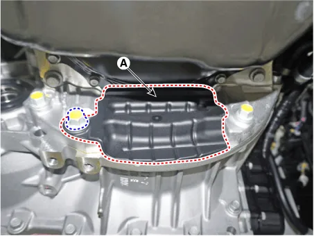
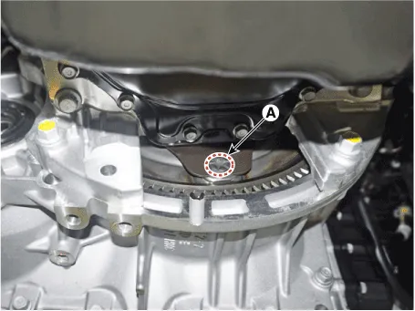
| 21. |
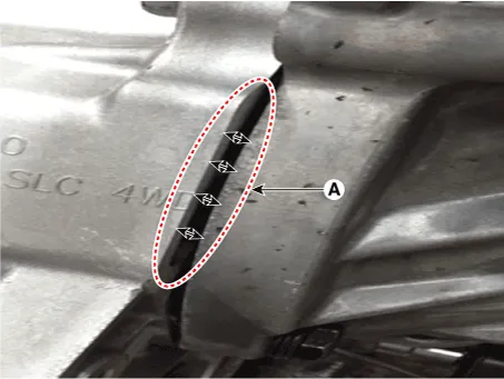
Loosen the mounting bolts (A) of the torque converter with rotating
the crankshaft.
|
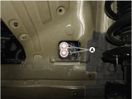
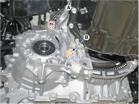
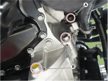
| 22. |
Remove the automatic transaxle with a jack after loonsening the mounting
bolts (A, B).
|
| Installation |
| 1. |
To install, reverse the removal procedure.
|


| 2. |
In case of the reinstallation.
|
| 3. |
In case of the replacing with a new automatic transaxle.
|

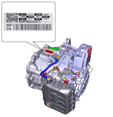
Components Location 1. ATF Injection plug (Eyebolt) 2. ATF injection plug gasket 3. ATF level check plug 4.
Other information:
Hyundai Santa Fe (TM) 2019-2023 Service and Repair Manual: Rear Power Mosfet. Repair procedures
Inspection 1. Turn the ignition switch ON. 2. Manually operate the control switch and measure the voltage of the blower motor. 3. Select the control switch to raise the voltage until it reaches high speed.
Hyundai Santa Fe (TM) 2019-2023 Service and Repair Manual: Troubleshooting
Trouble Symptom Charts Trouble Symptom 1 Trouble Symptom 2 Trouble symptom Probable cause Remedy The set vehicle speed varies greatly upward or downward "Surging" (repeated alternating acceleration and deceleration) occurs after set
Categories
- Manuals Home
- Hyundai Santa Fe Owners Manual
- Hyundai Santa Fe Service Manual
- Four Wheel Drive (4WD) mode selection
- Convenience features
- Front Radar Unit. Repair procedures
- New on site
- Most important about car
