Hyundai Santa Fe (TM): Air conditioning System / A/C Pressure Transducer. Repair procedures
| Inspection |
|

| 1. |
Turn the ignition switch OFF.
|
| 2. |
Install the refrigerant recovery/recycling/charging system.
(Refer to Air Conditioning System - "Repair procedures")
|
| 3. |
Turn ON the ignition switch, put into operation the air conditioner.
|
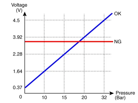
| 4. |
Calculate the reference voltage of the Recovery/Recycle/Recharge machine
high pressure value using the formula below.
|
| 5. |
Measure the sensor output voltage between terminal "1" and "2".
|
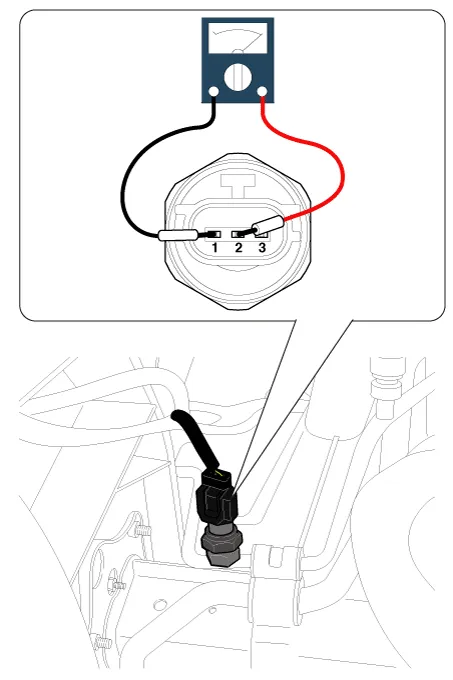
| 6. |
If the reference voltage value and the sensor output voltage value are
close to each other, the air conditioner pressure transducer is normal.
|
| 7. |
If 0V is output or the reference voltage value and sensor output voltage
value are not close to each other, replace the air conditioner pressure
transducer.
|

| Replacement |
| 1. |
Disconnect the negative (-) battery terminal.
|
| 2. |
Recover the refrigerant with a recovery/charging station.
|
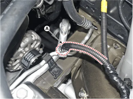
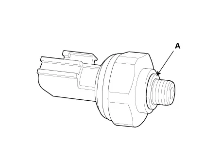
| 3. |
Disconnect the A/C pressure transducer connector (A).
|
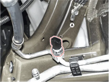
| 4. |
Remove the A/C pressure transducer (A).
|

| 5. |
Install in the reverse order of removal.
|
Description The A/C Pressure Transducer (APT) converts the pressure value of high pressure line into voltage value after measuring it.
Description The evaporator temperature sensor will detect the evaporator core temperature and interrupt compressor relay power in order to prevent evaporator from freezing by excessive cooling.
Other information:
Hyundai Santa Fe (TM) 2019-2023 Service and Repair Manual: Integrated Body Control Unit (IBU)
Description and operation Description Body Control Module Controls The Followings – Wiper & Washer Control – Defroster Control – Driving Control – Tailgate Control – Window Contr
Hyundai Santa Fe (TM) 2019-2023 Service and Repair Manual: Auto Lighting Control System
Description and operation Description It's a system that uses illumination sensor to automatically turn ON the tail lamp and head lamp based on the change in surrounding environment's illumination condition. It activates when the vehicle enters/exits tunnel, or when the illumination condition in surrounding environ
Categories
- Manuals Home
- Hyundai Santa Fe Owners Manual
- Hyundai Santa Fe Service Manual
- LCD Display
- Auto Hold. Warning messages
- Emission Control System
- New on site
- Most important about car
