Hyundai Santa Fe (TM): Engine Control System / Variable Intake Solenoid (VIS) Valve. Repair procedures
Hyundai Santa Fe (TM) 2019-2023 Service and Repair Manual / Engine Control/Fuel System / Engine Control System / Variable Intake Solenoid (VIS) Valve. Repair procedures
| Inspection |
| 1. |
Turn the ignition switch OFF.
|
| 2. |
Disconnect the VIS valve connector.
|
| 3. |
Measure resistance between VIS valve terminals 1 and 2.
|
| Removal |
| 1. |
Turn the ignition switch OFF and disconnect the battery negative (-)
cable.
|
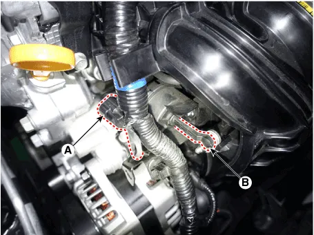
| 2. |
Disconnect the variable intake solenoid valve connector (A).
|
| 3. |
Disconnect the vacuum link (B) from the valve.
|
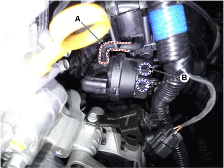
| 4. |
Disconnect the vacuum hoses (A) from the valve.
|
| 5. |
Remove the installation bolt (B), and then remove the valve from the
surge tank.
|
| Installation |
|

|
| 1. |
Installation is reverse of removal.
|
Circuit Diagram Harness Connector
Components and components location Components Location 1. Fuel tank 2. Fuel pump 3. Fuel filter 4. Fuel pump motor 5.
Other information:
Hyundai Santa Fe (TM) 2019-2023 Service and Repair Manual: A/C Pressure Transducer. Description and operation
Description The A/C Pressure Transducer (APT) converts the pressure value of high pressure line into voltage value after measuring it. By converted voltage value, engine ECU controls the cooling fan by operating it high speed or low speed.
Hyundai Santa Fe (TM) 2019-2023 Service and Repair Manual: Auto Defogging Sensor. Repair procedures
Inspection To inspect and diagnose the sensor, refer to Self-Diagnosis procedure and DTC guide. Replacement 1. Disconnect the negative (-) battery terminal. 2. Remove the rain sensor inner cover (A) and rain sensor cover (B).
Categories
- Manuals Home
- Hyundai Santa Fe Owners Manual
- Hyundai Santa Fe Service Manual
- Instrument cluster
- Blower
- Parking Brake System. Electronic Parking Brake (EPB)
- New on site
- Most important about car

Copyright © 2026 www.hsafe4.com - 0.0188