Hyundai Santa Fe (TM): Front Radar System / Smart Cruise Control (SCC) Switch. Schematic diagrams
| Circuit Diagram |
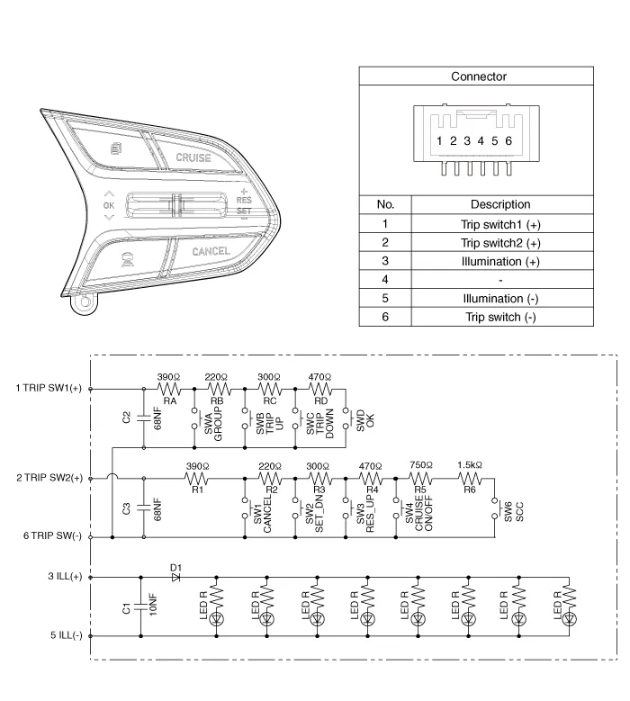
Components 1. Front radar unit 2. AVN Monitor 3. Smart cruise control switch
Inspection 1. Check for resistance between terminals in left switch position. [Audio/Bluetooth] Switch Connector terminal Resistance (± 3%) SEEK Up 1 - 6 430 Ω SEEK Down 1 - 6 1.
Other information:
Hyundai Santa Fe (TM) 2019-2023 Service and Repair Manual: Compressor oil. Repair procedures
Oil Specification 1. The R-134a or R-1234yf system requires synthetic (PAG) compressor oil whereas the R-12 system requires mineral compressor oil. The two oils must never be mixed. 2.
Hyundai Santa Fe (TM) 2019-2023 Service and Repair Manual: Surround View Monitor (SVM)
Description and operation Description Surround View Monitor (SVM) is the system that allows video monitoring of 360 degrees around the vehicle. The system includes 4 ultra optical camera mounted around the vehicle (front, both sides, rear).
Categories
- Manuals Home
- Hyundai Santa Fe Owners Manual
- Hyundai Santa Fe Service Manual
- Instrument cluster
- Blower
- Engine Electrical System
- New on site
- Most important about car
