Hyundai Santa Fe (TM): Engine Control System / Purge Control Solenoid Valve (PCSV). Repair procedures
| Inspection |
| 1. |
Turn the ignition switch OFF.
|
| 2. |
Disconnect the PCSV connector.
|
| 3. |
Measure resistance between the PCSV terminals 1 and 2.
|
| 4. |
Check that the resistance is within the specification.
|
| Removal |
| 1. |
Turn the ignition switch OFF and disconnect the battery negative (-)
cable.
|
| 2. |
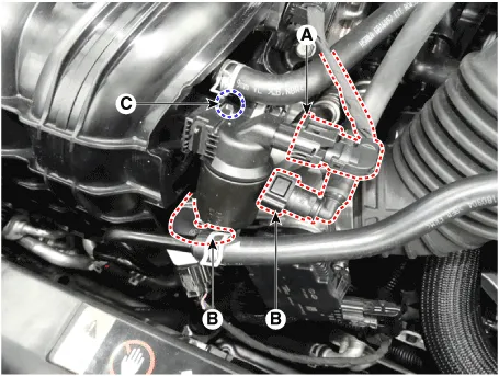
Disconnect the purge control solenoid valve connector (A).
|
| 3. |
Disconnect the vapor hoses (B) from the purge control solenoid valve.
|
| 4. |
Remove the bracket installation bolt (C), and then remove the valve
from the surge tank.
|
| Installation |
|

|
| 1. |
Installation is reverse of removal.
|
Circuit Diagram Harness Connector
Description CVVT (Continuous Variable Valve Timing) system advances or retards the valve opening and closing timing of the intake or the exhaust valve in accordance with the ECM control, calculated by the engine speed and the load.
Other information:
Hyundai Santa Fe (TM) 2019-2023 Service and Repair Manual: Power Tailgate Module
Description and operation Description Power tailgate is an electro-mechanical system designed to provide power opening and closing of the tailgate through the push of a button of a remote key (fob), console switch, inner switch or an outside handle switch of the tailgate.
Hyundai Santa Fe (TM) 2019-2023 Service and Repair Manual: Rear Occupant Alert
Description and operation Description The system detects the passenger in the vehicle and prevents the driver from getting off the vehicle with the passenger in the back. - 1st warning: If you open the driver's door after you open and then close the rear passenger and turn the engine off, the system provides warn
Categories
- Manuals Home
- Hyundai Santa Fe Owners Manual
- Hyundai Santa Fe Service Manual
- 4 Wheel Drive (4WD) System
- Battery. Specifications
- Hydraulic System
- New on site
- Most important about car
