Hyundai Santa Fe (TM): Air conditioning System / Photo Sensor. Repair procedures
| Inspection |
| 1. |
Emit intensive light toward the photo sensor using a lamp, and check
the output voltage change.
|
| 2. |
The voltage will rise with higher intensive light and reduce with lower
intensive light.
|
| Replacement |
| 1. |
Disconnect the negative (-) battery terminal.
|
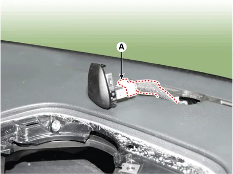
| 2. |
Using a screwdriver or remover, remove the photo sensor (A).
|
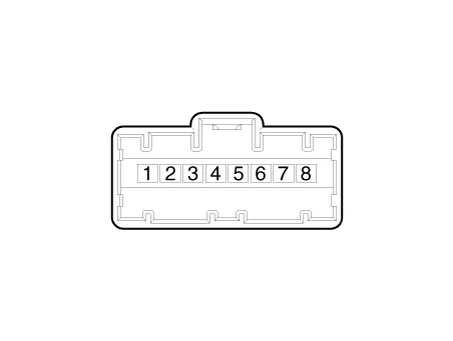
| 3. |
Press the lock pin, separate the photo sensor connector (A).
|
| 4. |
Install in the reverse order of removal.
|
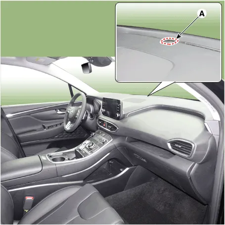
Description The photo sensor is located at the center of the defrost nozzles. The photo sensor contains a photovoltaic (sensitive to sunlight) diode.
Description The ambient temperature sensor is located at the front of the condenser and detects ambient air temperature. It is a negative type thermistor; resistance will increase with lower temperature, and decrease with higher temperature.
Other information:
Hyundai Santa Fe (TM) 2019-2023 Service and Repair Manual: Refrigerant Line. Repair procedures
Replacement [Front suction & Liquid pipe assembly] 1. If a compressor is available, the air conditioner is operated for a few minutes in the engine idle state and then the engine is stopped. 2.
Hyundai Santa Fe (TM) 2019-2023 Service and Repair Manual: Compressor. Description and operation
Description The compressor is the power unit of the A/C system. It is located on the side of engine block and driven by a V-belt of the engine. The compressor changes low pressure and low temperature refrigerant gas into high pressure and high temperature refrigerant gas.
Categories
- Manuals Home
- Hyundai Santa Fe Owners Manual
- Hyundai Santa Fe Service Manual
- Rear Disc Brake. Repair procedures
- Electronic Parking Brake (EPB)
- Emission Control System
- New on site
- Most important about car
