Hyundai Santa Fe (TM): Motor Driven Power Steering / Steering Gear Box. Repair procedures
| •
|
Be careful not to damage the parts located under the vehicle
(floor under cover, fuel filter, fuel tank and canister) when
raising the vehicle using the lift.
(Refer to General Information - "Lift and Support Points")
|
| •
|
Before replacing the R-MDPS, use the diagnostic device to read
the settings of the old ECU [R-MDPS Only]
|
|
|
1. |
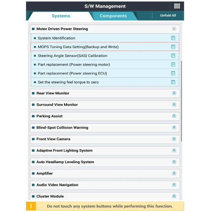
Perform the "ECU data backup" by diagnostic tool following in the order
below.
|
(1) |
Connect self - diagnosis connector (16pins) located in the lower
of driver side crash pad to self - diagnosis device.
|
|
(2) |
Turn the self - diagnosis device after key is ON.
|
|
(3) |
After Selecting the "vehicle model" and "MDPS system" on diagnostic
tool vehicle selection screen.
|
|
(4) |
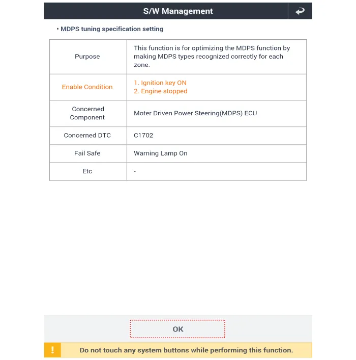
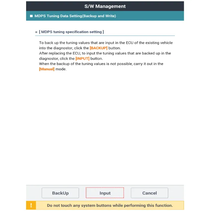
Select the "MDPS Tuning Data Setting(Backup and Write)"
|
|
(5) |
Follow the instructions shown on the screen.

|
|
|
2. |
Loosen the wheel nuts slightly.
Raise the vehicle, and make sure it is securely supported.
|
|
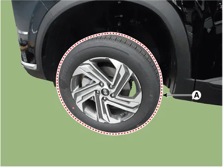
3. |
Remove the front wheel and tire (A) from the front hub.
|
Tightening torque :
107.9 - 127.5 N.m (11.0 - 13.0 kgf.m, 79.6 - 94.0 lb-ft)
|
|
• |
Be careful not to damage the hub bolts when removing
the front wheel and tire (A).
|
|
|
|
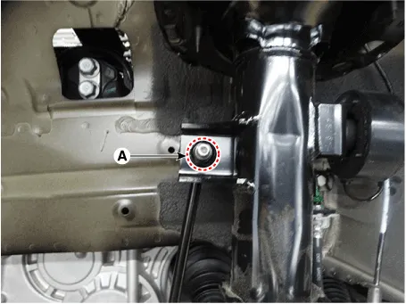
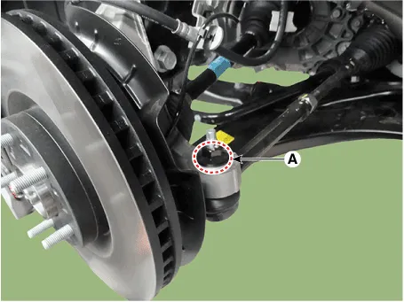
4. |
Disconnect the stabilizer link with the front strut assembly after loosening
the nut (A).
|
Tightening torque :
98.1 - 117.7 N.m (10.0 - 12.0 kgf.m, 72.3 - 86.8 lb-ft)
|
|
• |
When loosening the nut, fix the outer hexagon of stabilizer
bar link.
|
|
• |
Be careful not to damage the stabilizer link boots.
|
|
|
|
5. |
Remove the split pin and lock nut (A).
|
Tightening torque:
98.0 - 117.6 N.m (10.0 - 12.0 kgf.m, 72.3 - 86.7 lb-ft)
|
|
• |
Do not resuse lock nut.
|
|
|
|
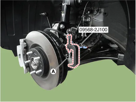
6. |
Remove the tie rod end ball joint (A) using the SST (09568-2J100).
|
|
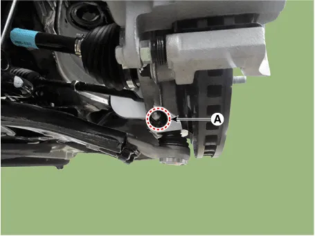
7. |
Remove the split pin and nut (A).
|
Tightening torque:
98.0 - 117.6 N.m (10.0 - 12.0 kgf.m, 72.3 - 86.7 lb-ft)
|
|
|
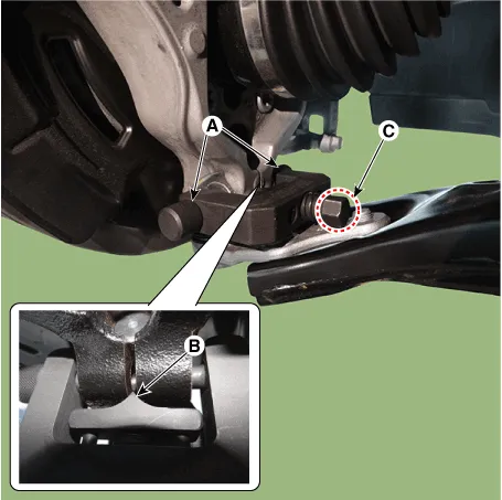
8. |
Remove the lower arm from the knuckle by using the SST (09568-4R100).
|
(1) |
Install the support bolt (A) from lower arm bolt hole.
|
|
(2) |
Install the support body (B) from front axle.
|
|
(3) |
Tighten the bolt (C).
|
|
|
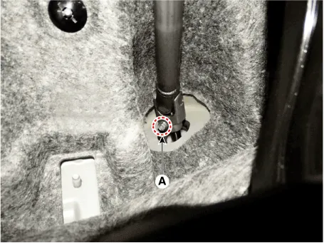
9. |
Loosen the bolt (A) and then disconnect the universal joint assembly
from the pinion of the steering gear box.
|
Tightening torque :
M8 BOLT : 32.4 - 37.3 N.m (3.3 - 3.8 kgf.m, 23.9 - 27.5 lb-ft)
M10 BOLT : 49.0 - 58.8 N.m (5.0 - 6.0 kgf.m, 36.2 - 43.4 lb-ft)
|
|
• |
Do not reuse the bolt.
|
|
• |
Lock the steering wheel in the straight ahead position
to prevent the damage of the clock spring inner cable.
|
|
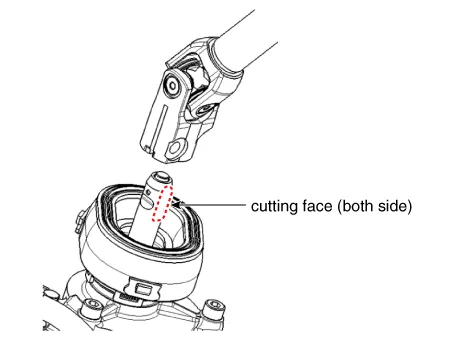
• |
Assemble so that the universal joint hole is inserted
matching the cut surface of the pinion shaft.
|
|
|
|
10. |
Remove the under cover.
(Refer to Engine Mechanical System - "Engine Room Under Cover")
|
|
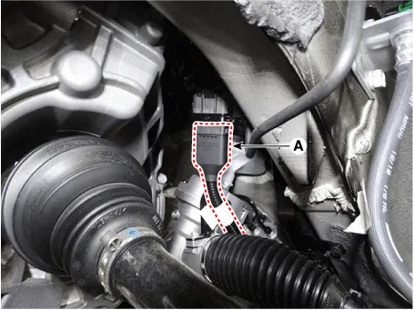
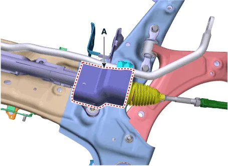
11. |
Disconnect the R-MDPS main connector (A). [R-MDPS Type only]
|
|
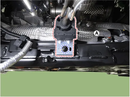
12. |
Remove the muffler rubber hanger (A) from the sub frame after loosening
the mounting bolt.
|
Tightening torque :
19.6 - 25.5 N.m (2.0 - 2.6 kgf.m, 14.5 - 18.8 lb-ft)
|
|
|
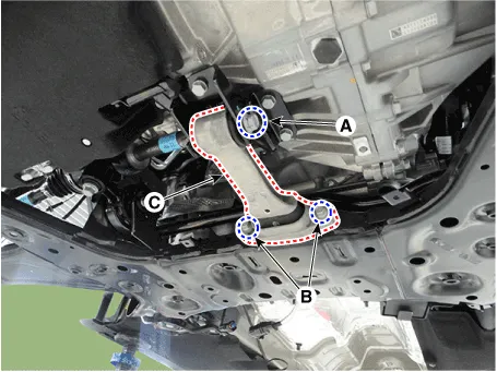
13. |
Remove the roll rod bracket (C) by loosening the bolt (A), (B).
|
Tightening torque
(A) : 107.9 - 127.5 N.m (11.0 - 13.0 kgf.m, 79.6 - 94.0 lb-ft)
(B) : 49.0 - 63.7 N.m (5.0 - 6.5 kgf.m, 36.2 - 47.0 lb-ft
|
|
• |
Set a transmission jack for safety.
|
|
|
|
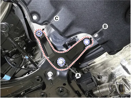
14. |
Remove the sub frame stay after loosening the mounting bolts (A, B)
and nut (C).
|
Tightening torque
(A) : 176.5 - 196.1 N.m (18.0 - 20.0 kgf.m, 130.2 - 144.7 b-ft)
(B) : 44.1 - 53.9 N.m (4.5 - 5.5 kgf.m, 32.5 - 39.8 lb-ft)
(C) : 44.1 - 53.9 N.m (4.5 - 5.5 kgf.m, 32.5 - 39.8 lb-ft)
|
|
|
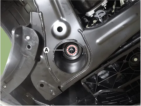
15. |
Loosen the sub frame mounting nuts (A).
|
Tightening torque
176.5 - 196.1 N.m (18.0 - 20.0 kgf.m, 130.2 - 144.7 b-ft)
|
|
|
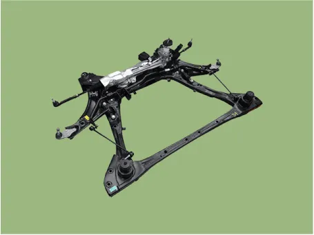
16. |
Remove the sub frame.
|
|
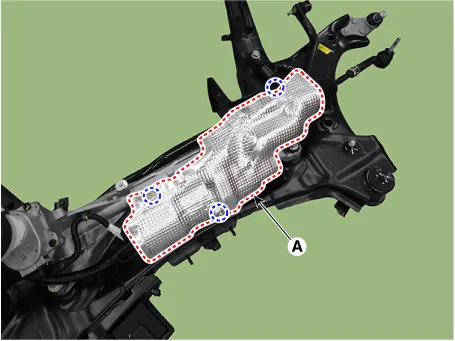
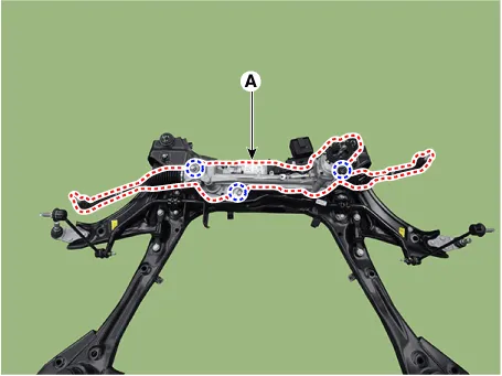
17. |
Remove the heat protector (A).
|
Tightening torque :
6.9 - 10.8 N.m (0.7 - 1.1 kgf.m, 5.1 - 8.0 lb-ft)
|
[R-MDPS]
[C-MDPS]
|
|
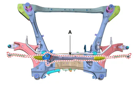
18. |
Remove the steering gearbox (A) from the front sub frame by loosening
the mounting bolts.
|
Tightening torque :
107.9 - 127.5 N.m (11.0 - 13.0 kgf.m, 79.6 - 94.0 lb-ft)
|
[R-MDPS]
[C-MDPS]
|
|
19. |
To install, reverse the removal procedures.
|
|
20. |
Check the alignment.
(Refer to Suspension System - "Alingment")
|
|
21. |
Conduct the "EPS Type Recognition" by diagnostic tool.
(Refer to MDPS motor - "Diagnosis with diagnostic tool")
|
|
22. |
Perform the "ECU data restore" by diagnostic tool following in the order
below. [R-MDPS Only]
|
(1) |
Connect self - diagnosis connector (16pins) located in the lower
of driver side crash pad to self - diagnosis device.
|
|
(2) |
Turn the self - diagnosis device after key is ON.
|
|
(3) |
After Selecting the "vehicle model" and "MDPS system" on diagnostic
tool vehicle selection screen.
|
|
(4) |
Select the "MDPS Tuning Data Setting(Backup and Write)"
|
|
(5) |
Follow the instructions shown on the screen.
|
|
| •
|
Do not disassembly the steering gear box.
|
| •
|
If disassembly the steering gear box, the quality(Noise / cleanliness
/ functions) is not guaranteed.
[C-MDPS]
[R-MDPS]
|
|
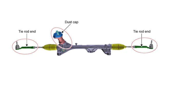
Tie rod end
|
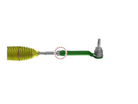
1. |
Remove the tie rod end after loosening the nut.
|
Tightening torque :
49.0 - 53.9 N.m (5.0 - 5.5 kgf.m, 36.2 - 39.8 lb-ft)
|
|
• |
Before removing the tie rod end, note by measuring the
length of the thread or marked with paint.
|
|
|
|
2. |
Replace with new parts.
|
|
3. |
Check the alignment.
(Refer to Tires / Wheels - "Alignment")
|
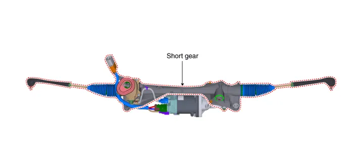
Power Pack And Short Gear
|
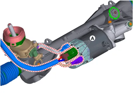
1. |
Disconnect the power pack connector (A).
|
|
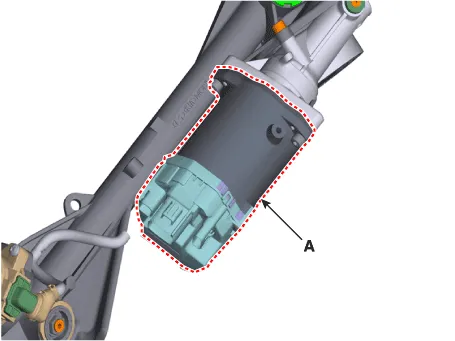
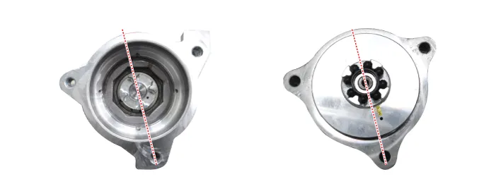
2. |
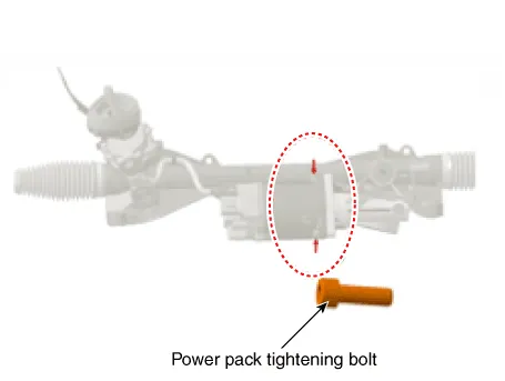
Replace the power pack (A) after loosening the mounting bolts.
|
Tightening torque :
19.6 - 23.5 N.m (2.0 - 2.4 kgf.m, 14.5 - 17.4 lb-ft)
|
|
|
3. |
In case of the power pack replacement, replace the power pack only and
reuse the existing short gear.
In case of the short gear replacement, replace the short gear only and
reuse the existing power pack.
|
• |
For assembly, the new product is basically coated with
grease for workability.
|
|
• |
When installing the power pack on the MDPS, install
it in the following direction.
|
|
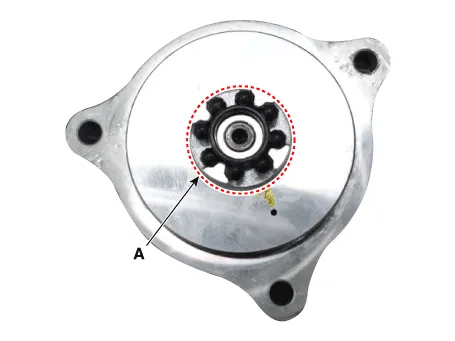
• |
Be sure to check whether the coupling (A) is assembled.
(If it cannot be used due to the existing coupling deformation/breakage,
request for new A/S and assemble.)
|
|
|
|
4. |
After replacing the power pack motor, "Steering Angle Sensor (SAS) Calibration"
and "MDPS Turning Data Setting (Backup and Write)" and "Set the steering
feel torque to zero" must be done
|
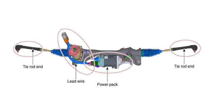
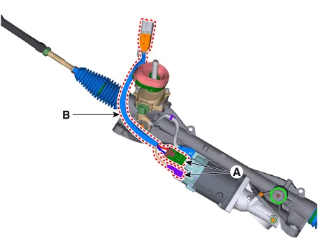
Lead Wire
|
1. |
Replace the lead wire (B) after disconnecting the power connector (A).
|
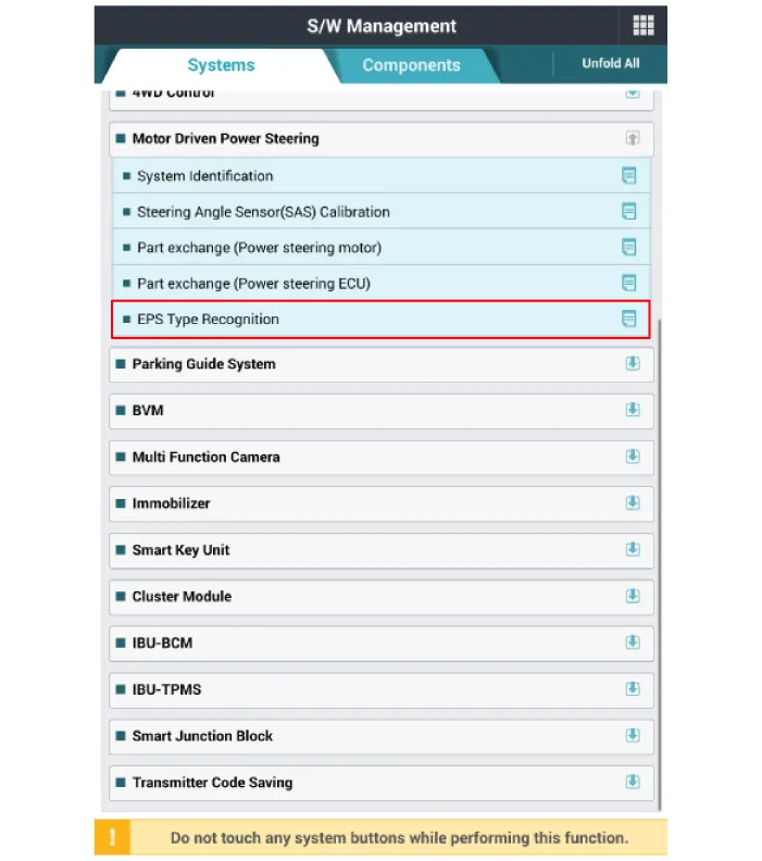
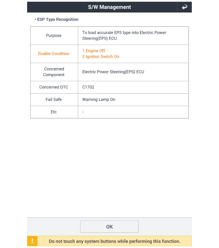
MDPS Type Recognition procedures
|
1. |
Connect the diagnostic tool diagnostic tool to the vehicle's self-diagnostic
connector.
|
|
2. |
Key on the Ignition switch.
|
|
3. |
After Selecting the "vehicle model" and "system", select the "EPS Type
Recognition" on diagnostic tool vehicle selection screen.
[MDPS Type Recognition]
[MDPS Type Recognition 1]
|
Components
[R-MDPS]
1. Tie rod end
2. Lead wire
3. Short gear
4. Power pack
[C-MDPS]
1.
Other information:
Description
•
PDW consists of 8 sensors (front : 4 units, rear : 4 units) that are
used to detect obstacles and transmit the result in three separate warning
levels, the first, second and third to IBU via LIN communication.
System Block Diagram
Component Parts And Function Outline
Component part
Function
Vehicle-speed sensor, ESP/ABS Control Module
Converts vehicle speed to pulse.
ECM
Receives signals from sensor and control switches.


