Hyundai Santa Fe (TM): ESP(Electronic Stability Program) System / Schematic diagrams
| Circuit Diagram |
ABS / ESC
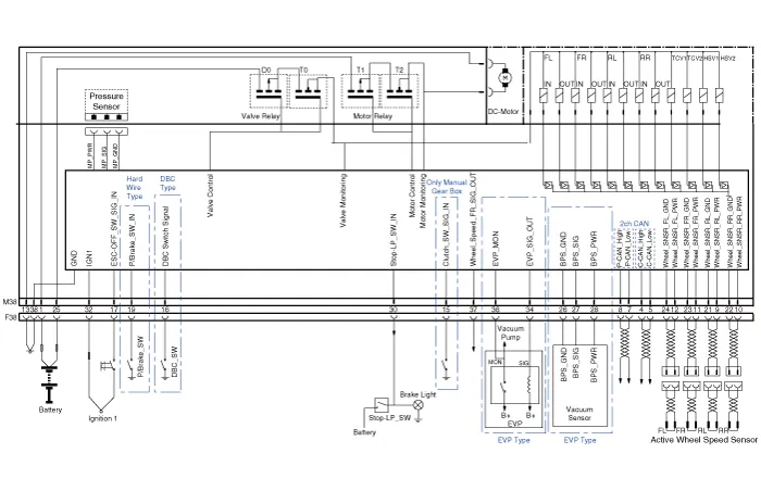
ESCi/ESCi+(EPB Integrated)

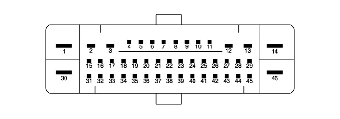
| Terminal Function |
ABS / ESC
|
PIN No |
Desciption |
Current |
Resistance |
|
1 |
Pump motor supply voltage |
60 A |
10 mΩ |
|
2 |
- |
- |
- |
|
3 |
- |
- |
- |
|
4 |
C-CAN High |
100 mA |
250 mΩ |
|
5 |
C-CAN Low |
100 mA |
250 mΩ |
|
6 |
- |
- |
- |
|
7 |
P-CAN Low |
100 mA |
250 MΩ |
|
8 |
P-CAN High |
100 mA |
250 MΩ |
|
9 |
Wheel speed sensor supply voltage (Left rear) |
100 mA |
250 MΩ |
|
10 |
Wheel speed sensor supply voltage (Right rear) |
100 mA |
250 MΩ |
|
11 |
Wheel speed sensor supply voltage (Right front) |
100 mA |
250 MΩ |
|
12 |
Wheel speed sensor supply voltage (Left front) |
100 mA |
250 MΩ |
|
13 |
Recycle pump ground |
40 A |
10 MΩ |
|
14 |
- |
- |
- |
|
15 |
Clutch stroke sensor signal |
1.2 mA |
250 MΩ |
|
16 |
DBC switch signal |
1.2 mA |
250 MΩ |
|
17 |
VDC OFF switch signal |
1.2 mA |
250 MΩ |
|
18 |
- |
- |
- |
|
19 |
Parking brake switch signal |
1.2 mA |
250 MΩ |
|
20 |
- |
- |
- |
|
21 |
Wheel speed sensor ground (Left rear) |
40 mA |
250 MΩ |
|
22 |
Wheel speed sensor ground (Right rear) |
40 mA |
250 MΩ |
|
23 |
Wheel speed sensor ground (Right front) |
40 mA |
250 MΩ |
|
24 |
Wheel speed sensor ground (Left front) |
40 mA |
250 MΩ |
|
25 |
Solenoid valve voltage |
30 A |
10 MΩ |
|
26 |
Brake pressure sensor ground |
60 mA |
10 MΩ |
|
27 |
Brake pressure sensor signal |
40 mA |
250 MΩ |
|
28 |
Brake pressure sensor power |
60 mA |
10 MΩ |
|
29 |
- |
- |
- |
|
30 |
Brake lamp switch |
1.2 mA |
250 MΩ |
|
31 |
- |
- |
- |
|
32 |
IGN 1 |
10 mA |
50 MΩ |
|
33 |
- |
- |
- |
|
34 |
Electronic vacuum pump output |
1 mA |
50 MΩ |
|
35 |
- |
- |
- |
|
36 |
Electronic vacuum pump motor monitor |
100 mA |
250 MΩ |
|
37 |
Wheel speed sensor output |
50 mA |
250 MΩ |
|
38 |
Solenoid valve ground |
30 A |
10 MΩ |
ESCi/ESCi+(EPB Integrated)
|
PIN No |
Desciption |
Current |
Resistance |
|
1 |
Pump motor supply voltage |
60 A |
10 MΩ |
|
2 |
Right rear EPB motor power |
15 A |
10 MΩ |
|
3 |
Right rear EPB motor ground |
15 A |
10 MΩ |
|
4 |
Brake pressure sensor ground |
60 mA |
10 MΩ |
|
5 |
- |
- |
- |
|
6 |
Electronic parking brake signal 1 [Connect] |
20 mA |
250 MΩ |
|
7 |
Electronic parking brake signal 2 [Connect] |
20 mA |
250 MΩ |
|
8 |
Electronic parking brake signal 3 [Release] |
20 mA |
250 MΩ |
|
9 |
Electronic parking brake signal 4 [Release] |
20 mA |
250 MΩ |
|
10 |
Brake pressure sensor signal |
40 mA |
250 MΩ |
|
11 |
Brake pressure sensor power |
60 mA |
10 MΩ |
|
12 |
Left rear EPB motor ground |
15 A |
10 MΩ |
|
13 |
Left rear EPB motor power |
15 A |
10 MΩ |
|
14 |
Solenoid valve ground |
40 A |
10 MΩ |
|
15 |
DBC switch signal |
1.2 mA |
250 MΩ |
|
16 |
- |
- |
- |
|
17 |
VDC OFF switch signal |
1.2 mA |
250 MΩ |
|
18 |
- |
- |
- |
|
19 |
C-CAN High |
100 mA |
250 MΩ |
|
20 |
C-CAN Low |
100 mA |
250 MΩ |
|
21 |
- |
|
|
|
22 |
P-CAN LOW |
100 mA |
250 MΩ |
|
23 |
P-CAN High |
100 mA |
250 MΩ |
|
24 |
- |
- |
- |
|
25 |
Wheel speed sensor supply voltage (Left rear) |
150 mA |
250 MΩ |
|
26 |
Wheel speed sensor supply voltage (Right rear) |
150 mA |
250 MΩ |
|
27 |
Wheel speed sensor supply voltage (Right front) |
150 mA |
250 MΩ |
|
28 |
Wheel speed sensor supply voltage (Left front) |
150 mA |
250 MΩ |
|
29 |
Electronic vacuum pump motor monitor |
100 mA |
250 MΩ |
|
30 |
Solenoid valve voltage |
40 A |
10 MΩ |
|
31 |
- |
- |
- |
|
32 |
- |
- |
- |
|
33 |
- |
- |
- |
|
34 |
Auto holding ON/OFF switch signal |
1.2 mA |
250 MΩ |
|
35 |
Brake lamp switch |
1.2 mA |
250 MΩ |
|
36 |
Electronic vacuum pump output |
1 A |
60 MΩ |
|
37 |
IGN 1 |
10 mA |
50 MΩ |
|
38 |
- |
- |
- |
|
39 |
- |
- |
- |
|
40 |
- |
- |
- |
|
41 |
Wheel speed sensor ground (Left rear) |
40 mA |
250 MΩ |
|
42 |
Wheel speed sensor ground (Right rear) |
40 mA |
250 MΩ |
|
43 |
Wheel speed sensor ground (Right front) |
40 mA |
250 MΩ |
|
44 |
Wheel speed sensor ground (Left front) |
40 mA |
250 MΩ |
|
45 |
Wheel speed sensor output (Right front) |
50 mA |
250 MΩ |
|
46 |
Recycle pump ground |
60 A |
10 MΩ |
Description of ESP ESP recognizes critical driving conditions, such as panic reactions in dangerous situations, and stabilizes the vehicle by wheel-individual braking and engine control intervention.
Failure Diagnosis 1. In principle, ESP and TCS controls are prohibited in case of ABS failure. 2.
Other information:
Hyundai Santa Fe (TM) 2019-2023 Service and Repair Manual: Components and components location
Hyundai Santa Fe (TM) 2019-2023 Service and Repair Manual: Components and components location
Component Location 1. Integrated Body Control Unit (IBU) 2. Ultrasonic Sensor ※ PDW function is applied alone, it is integrated into IBU (Integrated Body Control Unit). ※ PDW function is applied with RSPA function, it is integrated into ADAS_PRK controller.
Categories
- Manuals Home
- Hyundai Santa Fe Owners Manual
- Hyundai Santa Fe Service Manual
- Four Wheel Drive (4WD) operation
- Description and operation
- Unlocking your vehicle
- New on site
- Most important about car

Copyright © 2025 www.hsafe4.com - 0.0235