
Hyundai Santa Fe (TM): Engine Control System / Purge Control Solenoid Valve (PCSV). Repair procedures
| Inspection |
| 1. |
Turn the ignition switch OFF.
|
| 2. |
Disconnect the PCSV connector.
|
| 3. |
Measure resistance between the PCSV terminals 1 and 2.
|
| 4. |
Check that the resistance is within the specification.
|
| Removal |
| 1. |
Turn the ignition switch OFF and disconnect the battery negative (-)
cable.
|
| 2. |
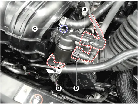
Disconnect the purge control solenoid valve connector (A).
|
| 3. |
Disconnect the vapor hoses (B) from the purge control solenoid valve.
|
| 4. |
Remove the bracket installation bolt (C), and then remove the valve
from the surge tank.
|
| Installation |
|

|
| 1. |
Installation is reverse of removal.
|
Circuit Diagram Harness Connector
Description CVVT (Continuous Variable Valve Timing) system advances or retards the valve opening and closing timing of the intake or the exhaust valve in accordance with the ECM control, calculated by the engine speed and the load.
Other information:
Hyundai Santa Fe (TM) 2019-2023 Service and Repair Manual: Power Door Locks
Components and components location Component Location 1. Driver power window main switch 2. IBU (Integrated Body Control Unit) 3. Door lock switch 4. Tailgate lock actuator & switch 5. Front door lock actuator & switch 6.
Hyundai Santa Fe (TM) 2019-2023 Service and Repair Manual: Blower
Blower Unit. Components and components location Components Location 1. Blower unit assembly Components 1. Blower unit assembly 2. Inlet case [LH] 3. Inlet seal 4.
Categories
- Manuals Home
- Hyundai Santa Fe Owners Manual
- Hyundai Santa Fe Service Manual
- Engine Electrical System
- Rear seats
- Vehicle Information, Consumer Information and Reporting Safety Defects
- New on site
- Most important about car
