Hyundai Santa Fe (TM): Power Door Mirrors / Power Door Mirror Switch. Repair procedures
Hyundai Santa Fe (TM) 2019-2023 Service and Repair Manual / Body Electrical System / Power Door Mirrors / Power Door Mirror Switch. Repair procedures
| Removal |
| 1. |
Disconnect the negative (-) battery terminal.
|
| 2. |
Remove the front left door trim.
(Refer to Body - "Front Door Trim")
|
| 3. |
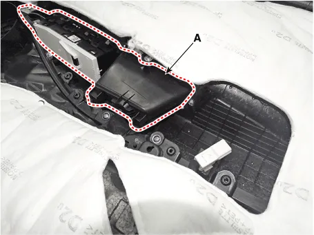
Remove the power window bezzel assembl (A) after loosening the mounting
screws.
|
| 4. |
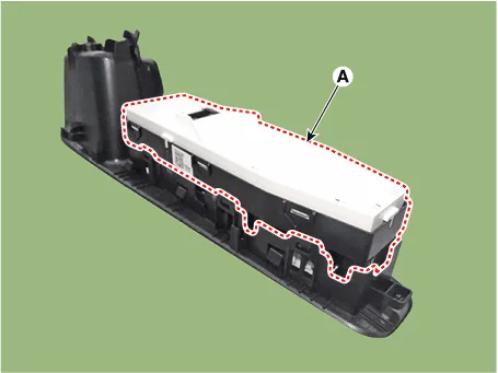
Remove the power window switch assembly (A) after loosening the mounting
screws.
|
| Installation |
| 1. |
Install the power mirror switch.
|
| 2. |
Install the front door trim after connecting the connector.
|
| 3. |
Connect the negative (-) battery terminal.
|
| Inspection |
Diagnosis with diagnostic tool
| 1. |
In the body electrical system, failure can be quickly diagnosed by using
the vehicle diagnostic system (diagnostic tool).
The diagnostic system (diagnostic tool) provides the following information.
|
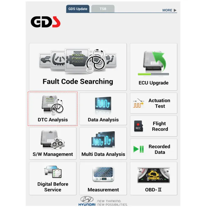
| 2. |
If diagnose the vehicle by diagnostic tool, select "DTC Analysis" and
"Vehicle".
|
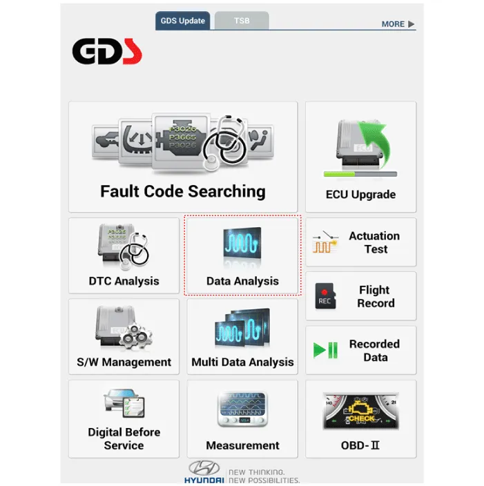
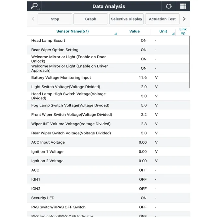
| 3. |
If check current status, select the "Data Analysis" and "Car model".
|
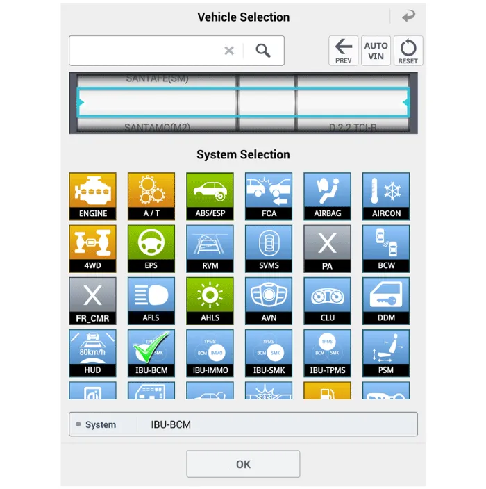
| 4. |
Select the 'IBU_BCM' to search the current state of the input/output
data.
|
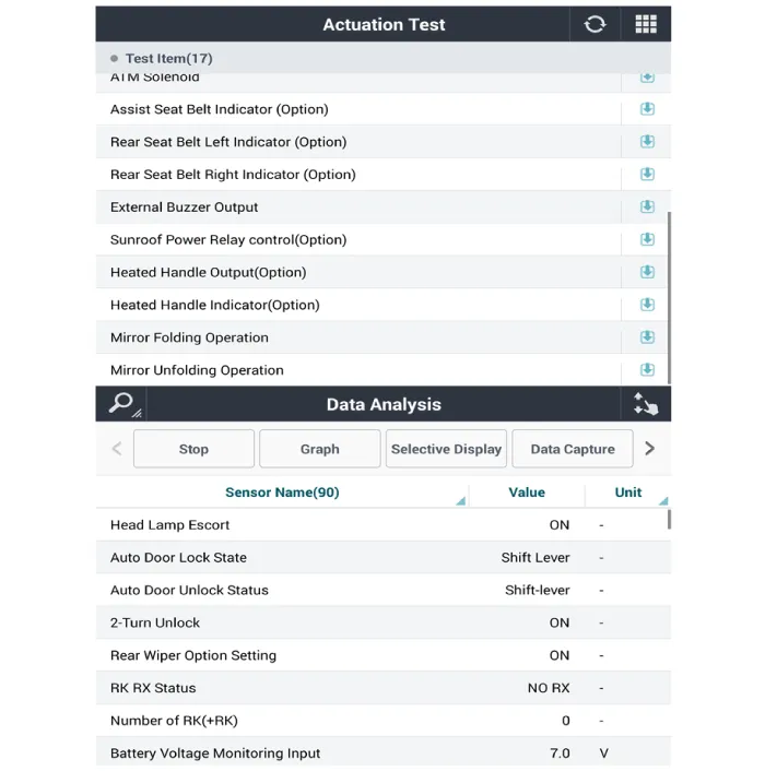
| 5. |
To forcibly actuate the input value of the module to be checked, select
option 'Actuation Test'.
|
Circuit Diagram
Removal 1. Disconnect (-) battery terminal. 2. Using a fastener remover (C), remove the mirror (A) as illustration below.
Other information:
Hyundai Santa Fe (TM) 2019-2023 Service and Repair Manual: Description and operation
Description and operation The System may be limited when • The radar sensor or camera is blocked with a foreign object or debris.
Hyundai Santa Fe (TM) 2019-2023 Service and Repair Manual: Front Radar Unit. Components and components location
Categories
- Manuals Home
- Hyundai Santa Fe Owners Manual
- Hyundai Santa Fe Service Manual
- Engine Mechanical System
- Instrument cluster
- Folding the side view mirror
- New on site
- Most important about car

Copyright © 2025 www.hsafe4.com - 0.02