Hyundai Santa Fe (TM): Body Electrical System / Power Door Mirrors
Hyundai Santa Fe (TM) 2019-2023 Service and Repair Manual / Body Electrical System / Power Door Mirrors
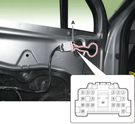
Components and components location
| Component Location |
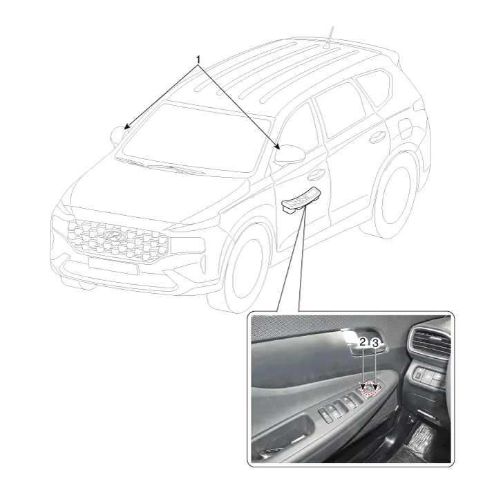
| 1. Power door
mirror 2. Power door mirror switch |
3. Power folding
mirror switch |
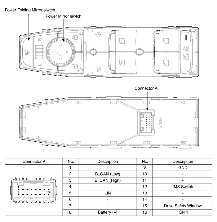
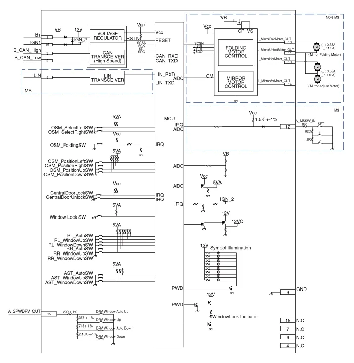
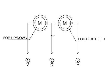
Power Door Mirror Switch. Schematic diagrams
| Circuit Diagram |
Power Door Mirror Switch. Repair procedures
| Removal |
| 1. |
Disconnect the negative (-) battery terminal.
|
| 2. |
Remove the front left door trim.
(Refer to Body - "Front Door Trim")
|
| 3. |
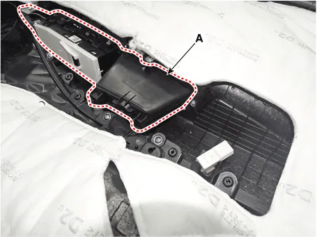
Remove the power window bezzel assembl (A) after loosening the mounting
screws.
|
| 4. |
Remove the power window switch assembly (A) after loosening the mounting
screws.
|
| Installation |
| 1. |
Install the power mirror switch.
|
| 2. |
Install the front door trim after connecting the connector.
|
| 3. |
Connect the negative (-) battery terminal.
|
| Inspection |
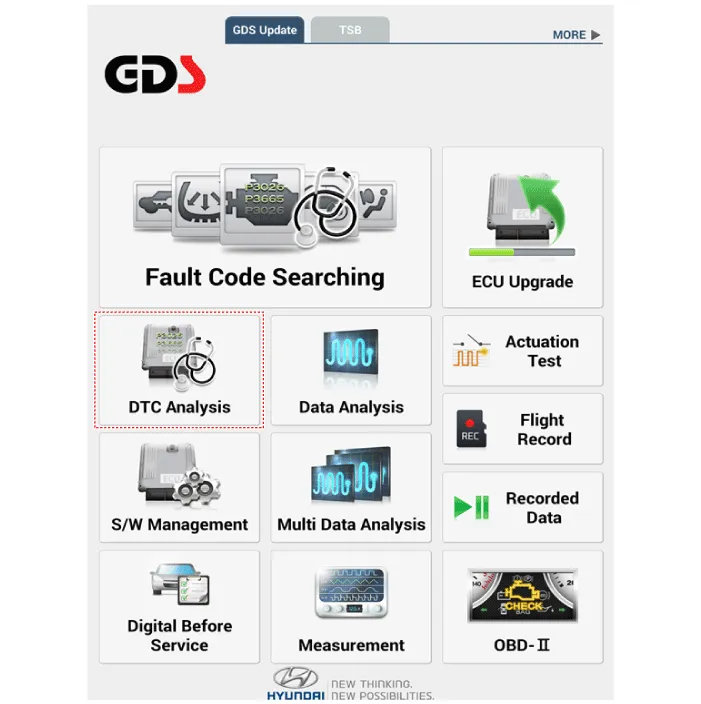
Diagnosis with diagnostic tool
| 1. |
In the body electrical system, failure can be quickly diagnosed by using
the vehicle diagnostic system (diagnostic tool).
The diagnostic system (diagnostic tool) provides the following information.
|
| 2. |
If diagnose the vehicle by diagnostic tool, select "DTC Analysis" and
"Vehicle".
|
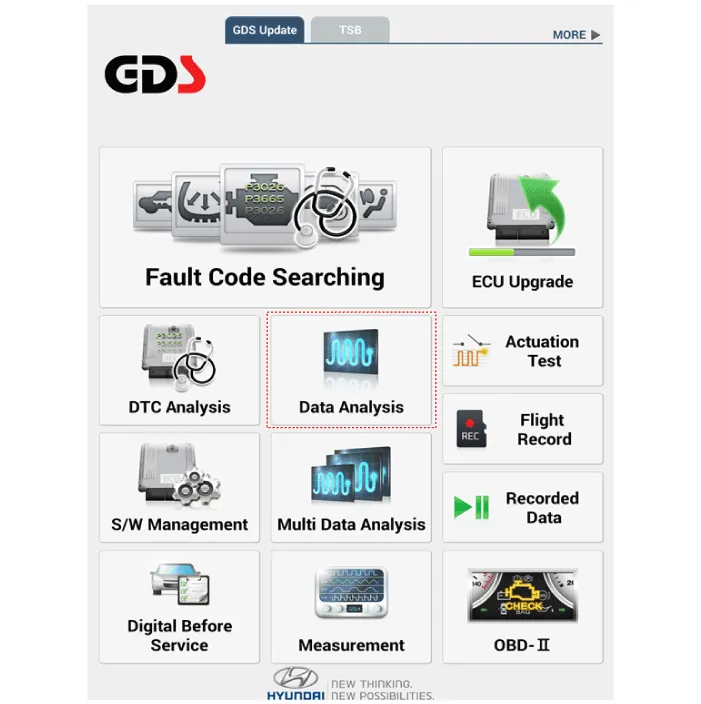
| 3. |
If check current status, select the "Data Analysis" and "Car model".
|
| 4. |
Select the 'IBU_BCM' to search the current state of the input/output
data.
|
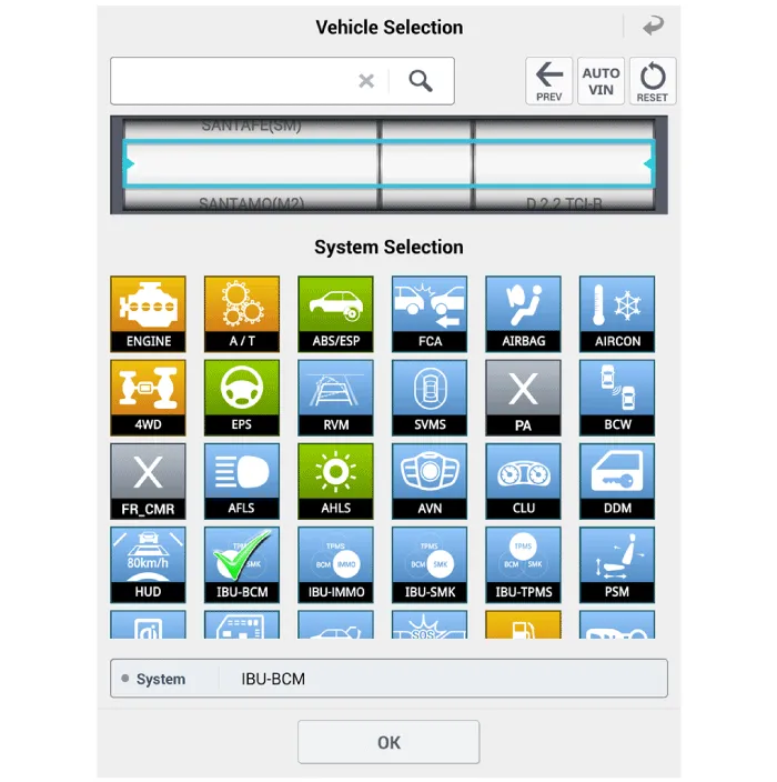
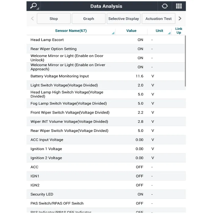
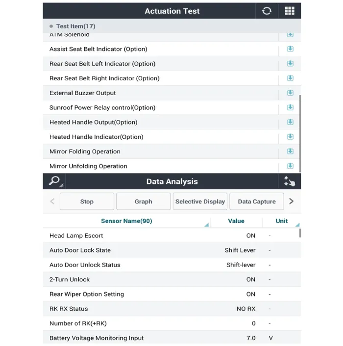
| 5. |
To forcibly actuate the input value of the module to be checked, select
option 'Actuation Test'.
|
Power Door Mirror Actuator. Repair procedures
| Removal |
| 1. |
Disconnect (-) battery terminal.
|
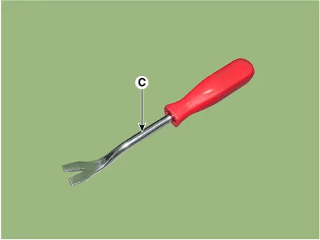
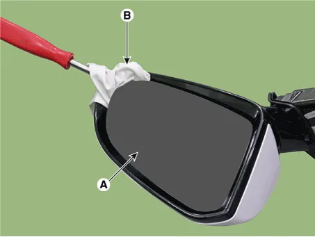
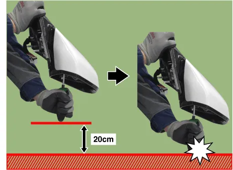
| 2. |
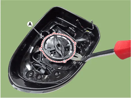
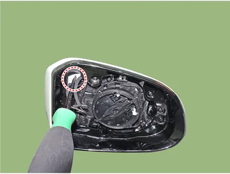
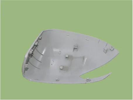
Using a fastener remover (C), remove the mirror (A) as illustration
below.
|

| 3. |
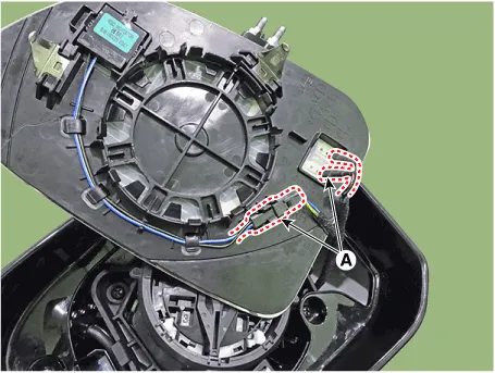
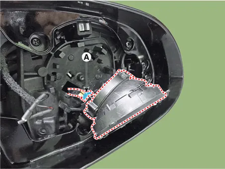
Disconnect heat wire connectors (A) and then remove the mirror.
|
| 4. |
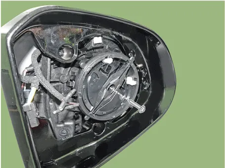
Remove the mirror actuator mounting screw.
|
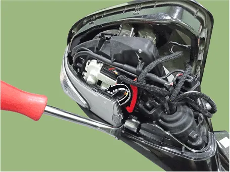
| 5. |
Insert the fastener remover into the end of the mirror actuator (A)
and lift it up.
|
| 6. |
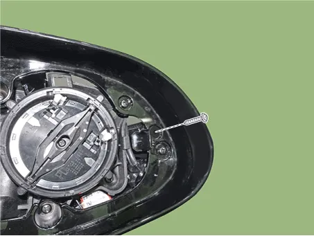
Disconnect the connector (A) and then remove the mirror actuator.
|
| Installation |
| 1. |
Connect the actuator connector and then install the mirror actuator.
|
| 2. |
Connect mirror heat wire connector and then install the mirror.
|
| 3. |
Connect (-) battery terminal then check if mirror works normally.
|
Power Door Mirror Assembly. Repair procedures
| Inspection |
| 1. |
Disconnect the negative (-) battery terminal.
|
| 2. |
Remove the door trim.
(Refer to Body - "Front Door Trim")
|
| 3. |
Disconnect the power door mirror connector (A) from the harness.
|
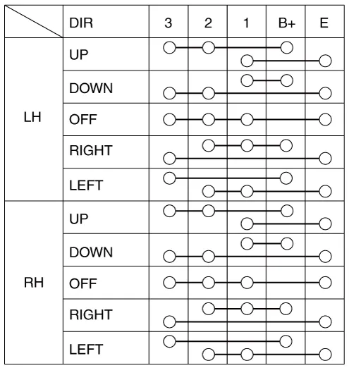
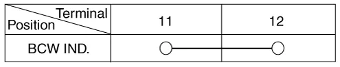
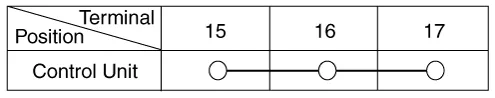
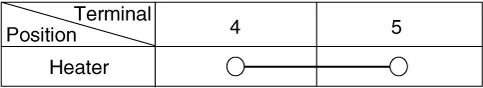
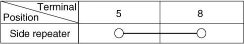
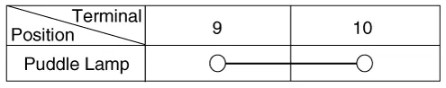
| 4. |
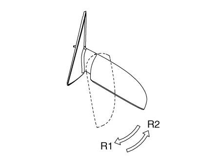
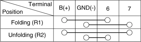
Apply battery voltage to each terminal as shown in the table and verify
that the mirror operates properly.
[Actuator]
BCW Indicator
Control Unit
Mirror Heater
Turn Signal Lamp
Puddle Lamp
Folding Mirror
|
| Removal |
| 1. |
Disconnect (-) battery terminal.
|
| 2. |
Remove front door trim.
(Refer to Body - "Front Door Trim")
|
| 3. |
Remove door mirror assembly.
(Refer to Body - "Outside View Mirror")
|
| 4. |
Using a fastener remover (C), remove the mirror (A) as illustration
below.
|
| 5. |
Disconnect heat wire connectors (A) and then remove the mirror.
|
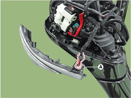
| 6. |
Remove the scalp.
|
| 7. |
Remove front cover and LED side repeater lamp lock screw.
|
| 8. |
Using a fastener remover, remove the LED side repeater lamp as illustration
below.
|
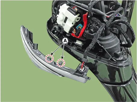
| 9. |
Disconnect the connector (A) and then remove the LED side repeater lamp.
|
| Installation |
| 1. |
Install the puddle lamp and LED side repeater lamp.
|
| 2. |
Install the scalp.
|
| 3. |
Connect mirror heat wire connector and BSD connector then mount mirror.
|
| 4. |
Install the door mirror assembly.
|
| 5. |
Connect (-) battery terminal then check if door mirror lamp works normally.
|
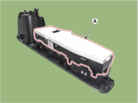
Components and components location Component Location 1. Driver power window main switch 2. IBU (Integrated Body Control Unit) 3.
Description and operation Function Of Safety Power Window When driver door power window auto-up switch is operated, safety function is activated.
Other information:
Hyundai Santa Fe (TM) 2019-2023 Service and Repair Manual: Special service tools
Hyundai Santa Fe (TM) 2019-2023 Service and Repair Manual: Controller
Heater & A/C Control Unit (Manual). Components and components location Component Connector Pin Function Pin No Connector A Connector B 1 Battery Low 2 ISG B+ Common 3
Categories
- Manuals Home
- Hyundai Santa Fe Owners Manual
- Hyundai Santa Fe Service Manual
- Hydraulic System
- Front Radar Unit. Repair procedures
- Lane Following Assist (LFA)
- New on site
- Most important about car

Copyright © 2026 www.hsafe4.com - 0.0221