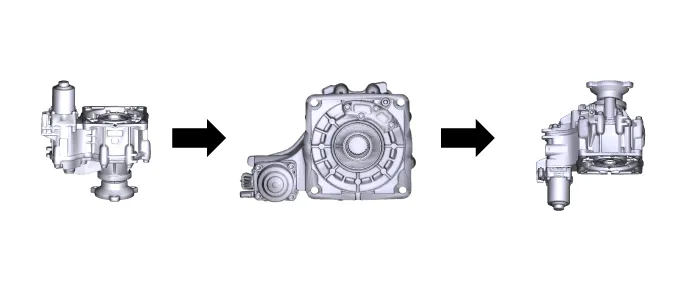
Hyundai Santa Fe (TM): Coupling Assembly / Oil hydraulic Motor(Actuator). Repair procedures
| Inspection |
|

| Oil Hydraulic Motor (Actuator) Inspection Procedure |
| Removal |
|

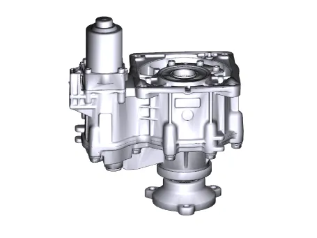
| 1. |
Remove the coupling assembly.
(Refer to 4 Wheel Drive (4WD) System - "Coupling Assembly")
|
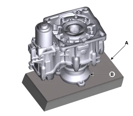
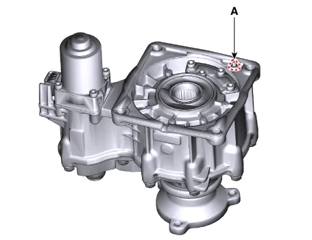
| 2. |
Keep going perpendicular state after remove the coupling assembly.
|
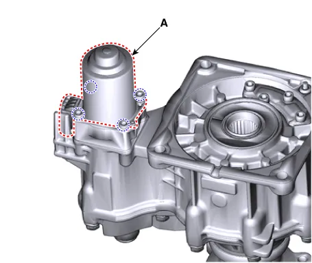
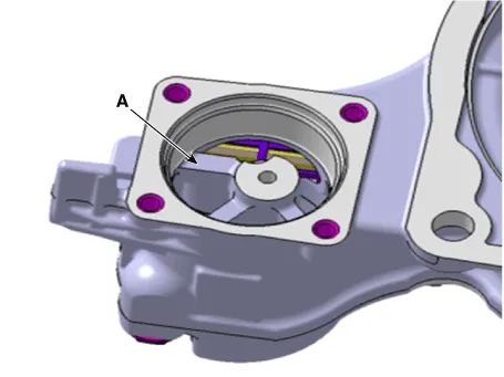
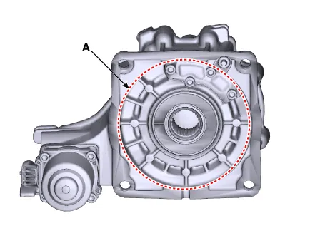
| 3. |
Remove the hydraulic motor (A) after loosening bolts with hex wrench.
|

| Installation |
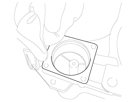
| 1. |
Before installation, wipe the surface with a clean cloth.
|
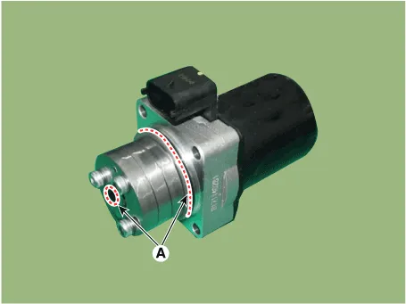
| 2. |
Check the O-rings (A) of the new hydraulic motor (actuators).
|
| 3. |
Tighten the bolts after install the hydraulic motor.
|
| 4. |
Wipe the flowed oil to around the surface with a clean cloth.
|
| 5. |
Install the coupling assembly.
(Refer to 4 Wheel Drive (4WD) System - "Coupling Assembly")
|
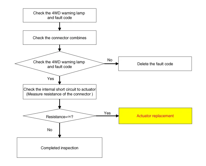
Circuit Diagram
Description The 4WD ECU makes a Motor Pump(Actuator) turn round for generating an oil pressure. And then it presses a multiple disk clutch and transfers the generated torque into rear wheels.
Other information:
Hyundai Santa Fe (TM) 2019-2023 Service and Repair Manual: Description and operation
Description and operation The System may be limited when • The radar sensor or camera is blocked with a foreign object or debris.
Hyundai Santa Fe (TM) 2019-2023 Service and Repair Manual: Parking Collision-Avoidance Assist (PCA). Repair procedures
Removal Parking Collision-Avoidance Assist (PCA) Unit 1. Disconnect the negative (-) battery terminal. 2. Remove the ADAS PRK Unit. (Refer to Advanced Driver Assistance System (ADAS) - "Driver Parking Assistance System") Parking Collision-Av
Categories
- Manuals Home
- Hyundai Santa Fe Owners Manual
- Hyundai Santa Fe Service Manual
- Unlocking your vehicle
- Front Wiper Motor. Components and components location
- Maintenance
- New on site
- Most important about car
