Hyundai Santa Fe: Driveshaft Assembly / Joint Assembly (Wheel side). Repair procedures
Hyundai Santa Fe (TM) 2019-2025 Service Manual / Driveshaft and axle / Driveshaft Assembly / Joint Assembly (Wheel side). Repair procedures
| Removal |
The type can replace the wheel side joint boot
| 1. |
Remove the front drive shaft.
(Refer to Driveshaft Assembly - "Front Driveshaft")
|
| 2. |
Remove the trans axle side joint.
(Refer to Driveshaft Assembly - "Transaxl Joint")
|
| 3. |
Remove the dynamic damper.
(Refer to Driveshaft Assembly - "Dynamic Damper")
|
| 4. |
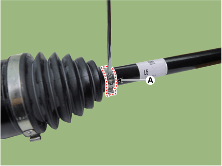
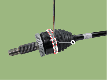
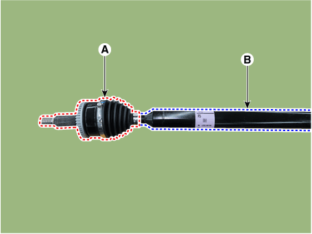
Remove the wheel side joint small diameter (A) and large diameter (B)
boot band using driver (-).
|
| 5. |
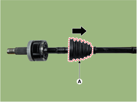
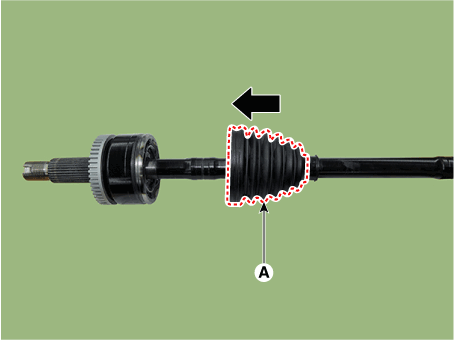
Remove the wheel side joint boot (A).
|
The type can not replace the wheel side joint boot
| 1. |
Remove the front drive shaft.
(Refer to Driveshaft Assembly - "Front Driveshaft")
|
| 2. |
Remove the trans axle side joint.
(Refer to Driveshaft Assembly - "Transaxl Joint")
|
| 3. |
Remove the dynamic damper.
(Refer to Driveshaft Assembly - "Dynamic Damper")
|
| 4. |
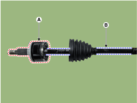
Replace the wheel side joint assembly (A) and shaft (B).
|
| Inspection |
| 1. |
Check the boot for water or foreign objects.
|
| 2. |
Replace any defective parts.
|
| Installation |
The type can replace the wheel side joint boot
|
| 1. |
Install the new boot (A) in the direction of the arrow.
|
| 2. |
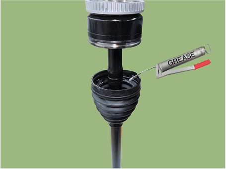
Apply the grease specified inside the boot.
|
| 3. |
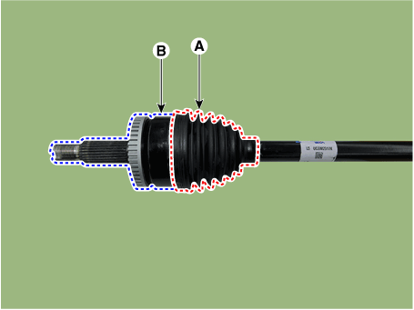
Install the wheel side boot (A) into the housing (B).
|
| 4. |
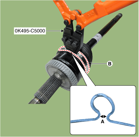
Install the large diameter boot band (B) using SST (0K495-C5000).
|
| 5. |
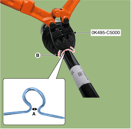
Install the small diameter boot band (B) using SST (0K495-C5000).
|
| 6. |
Install the dynamic damper. [If equipped]
(Refer to Driveshaft Assembly - "Dynamic Damper")
|
| 7. |
Install the transaxle side joint.
(Refer to Driveshaft Assembly - "Joint Assembly(Transaxle side)")
|
| 8. |
Install the front drive shaft.
(Refer to Driveshaft Assembly - "Front Driveshaft")
|
The type can not replace the wheel side joint boot
|
| 1. |
Replace the wheel side joint assembly (A) and shaft (B).
|
| 2. |
Remove the dynamic damper.
(Refer to Driveshaft Assembly - "Dynamic Damper")
|
| 3. |
Install the transaxle side joint.
(Refer to Driveshaft Assembly - "Joint Assembly(Transaxle side)")
|
| 4. |
Install the front drive shaft.
(Refer to Driveshaft Assembly - "Front Driveshaft")
|
 Joint Assembly (Transaxle side). Repair procedures
Removal
•
Drive shaft joints require special grease, so do not add any
other type of grease...
Other information:
Hyundai Santa Fe (TM) 2019-2025 Service Manual: Troubleshooting
..
Hyundai Santa Fe (TM) 2019-2025 Service Manual: Remote Smart Parking Assist (RSPA). Repair procedures
Removal ADAS Parking ECU (ADAS_PRK) 1. Disconnect the negative (-) battery terminal. 2. Remove the ADAS Parking ECU (ADAS_PRK). (Refer to Advanced Driver Assistance System (ADAS) - "ADAS Parking ECU (ADAS_PRK)") Parking/View switch • When removing with a flat-tip screwdriver or remover, wrap protective tape around the tools to prevent damage to components...
Categories
- Manuals Home
- 4th Generation Santa Fe Owners Manual
- 4th Generation Santa Fe Service Manual
- Warning and indicator lights
- Instrument panel overview
- Engine Control System
- New on site
- Most important about car
Engine oil pressure warning light. Low fuel level warning light
Engine oil pressure warning light
.png)
This warning light illuminates:
When the engine oil pressure is low.
If the engine oil pressure is low:
1. Drive carefully to the nearest safe location and stop your vehicle.
2. Turn the engine off and check the engine oil level (For more details, refer to “Engine Oil” section in chapter 9). If the level is low, add oil as required.
Copyright © 2025 www.hsafe4.com

