Hyundai Santa Fe (TM): Controller / Heater & A/C Control Unit (DATC). Repair procedures
| Self Diagnosis |
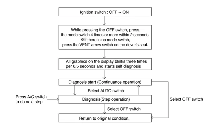
| 1. |
Self-diagnosis process.
|

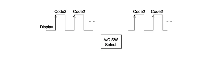
| 2. |
Fault code display
|


| 3. |
Self diagnostic code
|
| 4. |
FAIL SAFE
|
| Replacement |
| 1. |
Disconnect the negative (-) battery terminal.
|
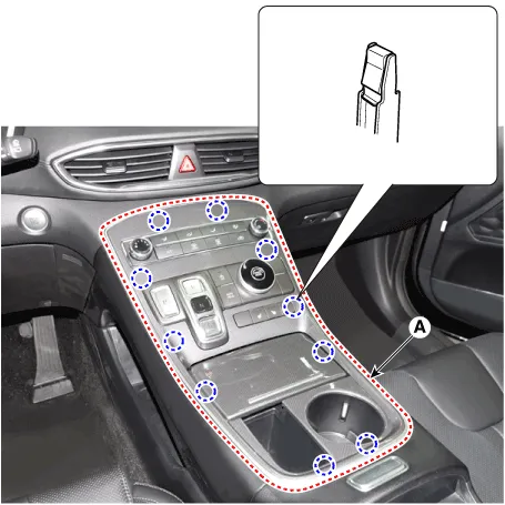
| 2. |
Remove the console upper cover (A).
|
| 3. |
Press the lock pin, separate the console upper cover connectors (A).
|
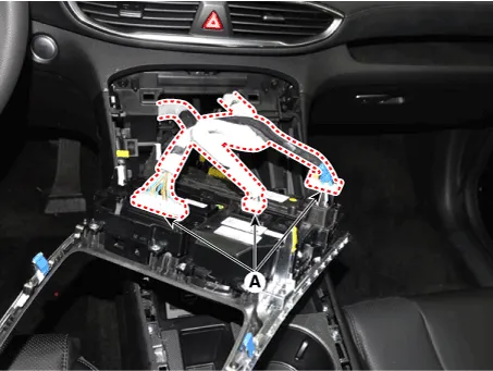
| 4. |
Loosen the mounting screws, remove the drive mode unit (A) and SBW switch
unit assembly (B).
|
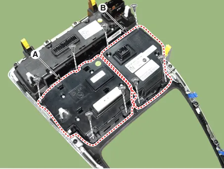
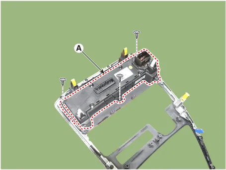
| 5. |
Loosen the mounting screws, remove the heater & A/C control unit (A).
|
| 6. |
Install in the reverse order of removal.
|

Component Connector Pin Function Pin No Connector A Connector B 1 Battery Temperature Actuator Feedback - Passenger 2 ISG B+ Temperature Actuator (Cool) - Passenger 3 ILL+ (TAIL) Temperature Actuator (Warm) - Passenger 4 Sensor REF (+5V) Defogging Actuator Feedback 5 Mode Actuator Feedback Defogging Actuator (Open) 6 Temperature Actuator Feedback - Driver Defogging Actuator (Close) 7 Intake Actuator Feedback - 8 Evaporator Temperature Sensor (+) - 9 Ambient Temperature Sensor (+) - 10 Mode Actuator (Vent) In-car sensor (+) 11 Mode Actuator (Defrost) PAB IGN1 12 Temperature Control Actuator (Cool) - Driver Defogging Sensor Glass Temperature 13 Temperature Control Actuator (Warm) - Driver - 14 Intake Actuator (Fresh Air) - 15 Intake Actuator (Recirculated Air) - 16 HTD (Rear Defrost) Ground 17 Rear Defogging Swich Rear Blower Motor (+) 18 - Rear Mosfer (Drain Feedback) 19 - Rear Mosfer (Gate) 20 ILL - (RHEO) - 21 IGN 2 - 22 IGN 1 - 23 Blower Motor (+) - 24 Photo Sensor (-)_LEFT LIN BUS (Climate control) 25 Photo Sensor (-)_RIGHT - 26 Defogging Sensor Data - 27 Defogging Sensor SCL - 28 - - 29 PTC Relay 2 (DIESEL) / Driver Seat Signal PWM PTC Relay (GASOLINE) 30 PTC ON Signal (DIESEL) / - - (GASOLINE) 31 - Rear C-LINE 32 - - 33 P_CAN (HIGH) 34 P_CAN (LOW) 35 Mosfet (DRAIN F/B) 36 Mosfet (GATE) 37 ECV (+) 38 ECV (-) Ground 39 Sensor Ground 40 Ground
Component [Connector Pin Function] Pin No Connector A 1 Battery (+) 2 IGN2 3 ILL+ (TAIL) 4 REAR C-LINE 5 ILL- (RHEO) 6 Ground
Other information:
Hyundai Santa Fe (TM) 2019-2023 Service and Repair Manual: Front Radar Unit. Specifications
Hyundai Santa Fe (TM) 2019-2023 Service and Repair Manual: Troubleshooting
Troubleshooting Diagnosis with Diagnostic tool 1. In the body electrical system, failure can be quickly diagnosed by using the vehicle diagnostic system (Diagnostic tool). The diagnostic system (Diagnostic tool) provides the following information.
Categories
- Manuals Home
- Hyundai Santa Fe Owners Manual
- Hyundai Santa Fe Service Manual
- Front Radar Unit. Repair procedures
- General Information
- Rear Bumper Assembly. Repair procedures
- New on site
- Most important about car
